

2 layers355.6 × 97.8 mm

 TorBorve/Drone-Launcher
This folder contains all the Schematics and PCB designs for the drone launcher. KiCAD has been used to make these. Please download it to view these files.
Drone Launcher is an open-source printed circuit board by TorBorve, from the TorBorve/Drone-Launcher repository on GitHub. It is a 2-layer board of 117.9 × 75.7 mm with 36 parts on 71 nets, routed with 265 tracks and 16 vias.
It is built around the TSR 1-2450 and TEENSY 4.1. Its parts include 19 connectors, 5 resistors, 3 ICs, 3 diodes and 1 capacitor. It belongs with the robots and motor control boards and the NXP (LPC, Kinetis, i.MX RT) boards of this library.
This folder contains all the Schematics and PCB designs for the drone launcher. KiCAD has been used to make these. Please download it to view these files.
There are two processing units in the drone launcher: Teensy 4.1 and Odroid C2. These two communicate over serial using a micro USB cabel. The Odroid is also connected to a Rajant radio using an ethernet cabel. The Teensy is placed on a PCB which connects it to all the peripherals.
List over PCB connections:
Please refere to the pcb schematic to figure out the pinouts of the different connectors.
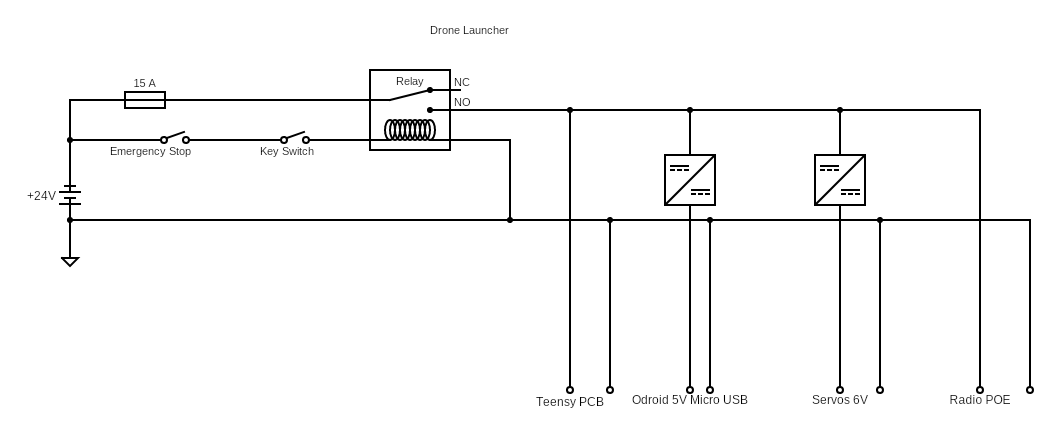
A 6s LiPo battery is used to power the system. This power goes though a 15 A fuse and a Relay. The Relay coil is connected to a emergency stop button and a key switch. If any of these are not turned no the system will not have any power. After going though the relay the power is distributed to the different devices.
Power Devices:
Teensy PCB, connect battery to XT60 plug
Odorid, 5V@2A needed, connect micro usb plug from switching regulator
Rajant Radio, PoE 8-60V?, connect ethernet cabel to battery voltage
Servos, 6V, use step down regulators to provide power
| Qty | Value | Footprint | References |
|---|---|---|---|
| 4 | ~ | MountingHole:MountingHole_3.2mm_M3 | MH1, MH2, MH3, MH4 |
| 3 | 1k | Resistor_SMD:R_1206_3216Metric | R3, R6, R7 |
| 2 | RED | LED_SMD:LED_1206_3216Metric | D1, D4 |
| 1 | 120K | Resistor_SMD:R_1206_3216Metric | R2 |
| 1 | 220n | Capacitor_SMD:C_1206_3216Metric | C1 |
| 1 | 820K | Resistor_SMD:R_1206_3216Metric | R1 |
| 1 | Arming Swtich | Connector_JST:JST_XH_B2B-XH-A_1x02_P2.50mm_Vertical | J6 |
| 1 | BTNS F1R1 | Connector_JST:JST_XH_B6B-XH-A_1x06_P2.50mm_Vertical | J13 |
| 1 | BTNS F1R2 | Connector_JST:JST_XH_B6B-XH-A_1x06_P2.50mm_Vertical | J14 |
| 1 | BTNS F2R1 | Connector_JST:JST_XH_B6B-XH-A_1x06_P2.50mm_Vertical | J15 |
| 1 | BTNS F2R2 | Connector_JST:JST_XH_B6B-XH-A_1x06_P2.50mm_Vertical | J16 |
| 1 | BTNS F3R1 | Connector_JST:JST_XH_B6B-XH-A_1x06_P2.50mm_Vertical | J17 |
| 1 | BTNS F3R2 | Connector_JST:JST_XH_B6B-XH-A_1x06_P2.50mm_Vertical | J18 |
| 1 | GPS | Connector_JST:JST_XH_B6B-XH-A_1x06_P2.50mm_Vertical | J19 |
| 1 | GREEN | LED_SMD:LED_1206_3216Metric | D5 |
| 1 | I2C IMU | Connector_JST:JST_XH_B4B-XH-A_1x04_P2.50mm_Vertical | J10 |
| 1 | I2C LCD | Connector_JST:JST_XH_B4B-XH-A_1x04_P2.50mm_Vertical | J11 |
| 1 | I2C Odroid | Connector_JST:JST_XH_B2B-XH-A_1x02_P2.50mm_Vertical | J9 |
| 1 | LED Strip Drone | Connector_JST:JST_XH_B3B-XH-A_1x03_P2.50mm_Vertical | J7 |
| 1 | LED strip battery | Connector_JST:JST_XH_B3B-XH-A_1x03_P2.50mm_Vertical | J4 |
| 1 | LOGO | LOGO | G*** |
| 1 | Menu Btns | Connector_JST:JST_XH_B8B-XH-A_1x08_P2.50mm_Vertical | J5 |
| 1 | PWR IN | Connector_XT60:AMASS_XT60-M | J20 |
| 1 | SPI | Connector_JST:JST_XH_B4B-XH-A_1x04_P2.50mm_Vertical | J8 |
| 1 | Servos F1 | Connector_JST:JST_XH_B4B-XH-A_1x04_P2.50mm_Vertical | J1 |
| 1 | Servos F2 | Connector_JST:JST_XH_B4B-XH-A_1x04_P2.50mm_Vertical | J2 |
| 1 | Servos F3 | Connector_JST:JST_XH_B4B-XH-A_1x04_P2.50mm_Vertical | J3 |
| 1 | TSR_1-2450 | Converter_DCDC:Converter_DCDC_TRACO_TSR-1_THT | U1 |
| 1 | Teensy4.1 | teensy:Teensy41 | U2 |
| 1 | ~ | Adafruit_MCP23017_Breakout:Adafruit_MCP23017_Breakout | U3 |
It measures 117.9 × 75.7 mm and has 2 copper layers, 1.6 mm thick.
36 parts, built around the TSR 1-2450 and TEENSY 4.1. The full list of its parts is on this page, with links to each part's symbol and footprint where PCBKit's library has them.
From the TorBorve/Drone-Launcher repository on GitHub, at the commit this page was made from: the board is electronics/drone_launcher.kicad_pcb and its schematic electronics/drone_launcher.kicad_sch. PCBKit opens the board in the browser, with nothing to install.
Its repository states no licence, so its author keeps all rights: ask TorBorve before reusing the design.


corygrant/dingoPDM
Hardware - dingoPDM is an open source, affordable automotive PDM (Power Distribution Module). Pre-assembled and tested units are available or the design can be used to build a DIY version.

hberntsen/mhi-ac-ctrl-esp32
Control MHI Airconditioning locally using your own ESP32 series chip!


