2 layers203.2 × 254 mm
Orange Line
tomunderwood99/CharlieBoard
An open-source PCB map showing Boston's subway system
41 parts43MIT

 tomunderwood99/CharlieBoard43
An open-source PCB map showing Boston's subway system
Production red line new silk is an open-source printed circuit board by tomunderwood99, from the tomunderwood99/CharlieBoard repository on GitHub, published under the MIT licence. It is a 2-layer board of 203.2 × 254 mm with 48 parts on 50 nets, routed with 246 tracks and 47 vias.
Its parts include 47 ICs and 1 connector. It belongs with the lEDs and displays boards of this library.





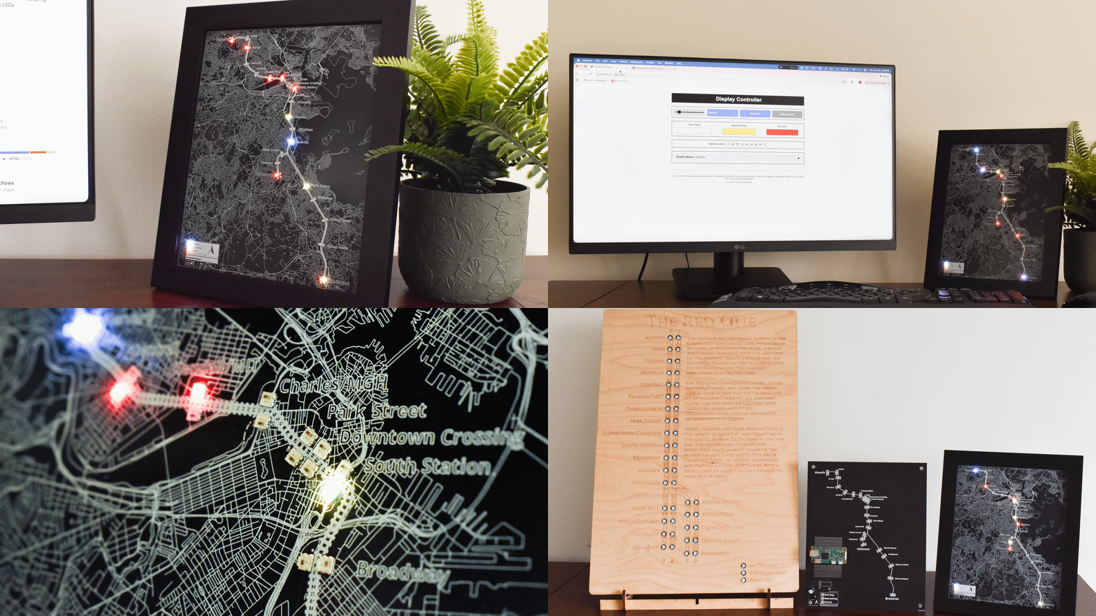
An open-source LED display system for the MBTA that runs on Raspberry Pi Zero 2W with WS2812B LEDs. Features real-time transit data visualization, web control interface, and geographically accurate station mapping. PCBs for the Red, Orange, and Blue line are live! Green line in progress :)
Prerequisites:
For hardware assembly instructions, see the Hardware Assembly Guide.
Run the following commands to install and initialize the display.
sudo apt update && sudo apt install -y git python3-pip

cd ~
git clone --filter=blob:none --sparse https://github.com/tomunderwood99/CharlieBoard.git

cd CharlieBoard
git sparse-checkout set --no-cone '/*' '!hardware'

chmod +x deployment/quick_start/setup_mbta_controller.sh

# Optional: use flags to set custom recovery wifi settings:
# --with-wifi-helper
# --ap-ssid "CustomWifiName"
# --ap-password "YourStrongPassword"

sudo ./deployment/quick_start/setup_mbta_controller.sh
The setup script will prompt for your MBTA API key and various setting inputs. After completion, access the web interface at http://your-hostname.local:8000 on your local network. Settings can be changed from the web interface or from the command line using the charlieboard command. See the CLI reference for details.
Optional enhancement: Set up a reverse proxy to access the web interface at http://hostname.local without the port number. See the nginx reverse proxy setup guide.
Note: The sparse-checkout excludes the hardware/ directory (PCB design files) to speed up cloning. This setting persists across future git pull operations. If you need the hardware files, run: git sparse-checkout disable
| Component | Notes |
|---|---|
| Raspberry Pi Zero 2W | Main controller |
| WS2812B LEDs | Custom PCB (~$120 for 5) or LED strips (~$20) |
| 5V 4A Power Supply | Powers Pi and LEDs |
| MicroSD Card (16GB+) | For OS and software |
| Display Enclosure | Picture frame or custom case |
Total Cost: $50–180 depending on LED choice
Complete PCB design files (Gerber + KiCad) are available in hardware/PCB Production/. See the Bill of Materials for detailed pricing and sourcing.
| Guide | Description |
|---|---|
| Quick Start Guide | Step-by-step setup walkthrough |
| Terminal CLI | Change settings from SSH without the web UI |
| Complete Setup Guide | Detailed manual configuration |
| Bill of Materials | Hardware pricing and sourcing |
| Hardware Assembly | PCB assembly instructions |
| Operations & Troubleshooting | Maintenance and problem solving |
| Transit System Adaptation | Adapt for other transit systems |
| Map Making with QGIS | Create custom transit maps (example project) |
Contributions are welcome! Please:
git checkout -b feature/amazing-feature)git commit -m 'Add amazing feature')Follow existing code style, update documentation for new features, and add comments for complex logic. Contributions to software are under the MIT License; contributions to hardware/ design files are under CERN-OHL-S, as described in License.
This repository uses two licenses:
| Scope | License | Full text |
|---|---|---|
Software (Python, scripts, configs, docs outside hardware/, and everything except the hardware/ tree) | MIT License | LICENSE |
hardware/ (PCB designs, KiCad projects, Gerbers, and related production files in this directory) | CERN Open Hardware Licence v2 — Strongly Reciprocal (CERN-OHL-S) | LICENSE-CERN-OHL-S |
Third-party materials bundled under hardware/ may carry their own licenses (see notices in those subfolders).
Copyright © 2025 Thomas Underwood
This project was developed with the assistance of AI coding tools. All code has been reviewed, tested, and validated on actual hardware.
This project uses data from:
All data is provided "as is" without warranties. This project is not affiliated with, endorsed by, or sponsored by MBTA, MassDOT, MassGIS, or the Commonwealth of Massachusetts.
sudo journalctl -u mbta_display -n 100| Qty | Value | Footprint | References |
|---|---|---|---|
| 47 | WS2812-2020 | WS2812_2020:LED_WS2812-2020 | U2, U10, U11, U12, U13, U14, U15, U16, U17, U18, U19, U20, U21, U22, U23, U24 +31 |
| 1 | Conn_01x03_MountingPin | Connector_JST:JST_EH_B3B-EH-A_1x03_P2.50mm_Vertical | J4 |
tomunderwood99/CharlieBoard
An open-source PCB map showing Boston's subway system

tomunderwood99/CharlieBoard
An open-source PCB map showing Boston's subway system

hackclub/OnBoard
💡 Join 1,000 teenagers and make your first PCB with a $100 grant!

adamws/kicad-kbplacer
KiCad plugin for automatic keyboard's key placement and routing


softerhardware/Hermes-Lite2
A second generation low-cost amateur HF software defined radio transceiver.

CRImier/MyKiCad
My KiCad boards. Can't be bothered uploading individually anymore, so here you go.

loxodes/vna
Under development open hardware microwave vector network analyzer

fellesverkstedet/fabricatable-machines
Motion systems for flexible digital fabrication and research. Easy to fabricate and customize. Documentation: https://github.com/fellesverkstedet/fabricatable-machines/wiki
It measures 203.2 × 254 mm and has 2 copper layers, 1.6 mm thick.
48 parts. The full list of its parts is on this page, with links to each part's symbol and footprint where PCBKit's library has them.
From the tomunderwood99/CharlieBoard repository on GitHub, at the commit this page was made from: the board is hardware/PCB Production/KICAD Files/Red Line/production_red_line_new_silk.kicad_pcb and its schematic hardware/PCB Production/KICAD Files/Blue Line/Blue Line.kicad_sch. PCBKit opens the board in the browser, with nothing to install.
Its repository publishes it under the MIT licence: you may reuse it on that licence's terms (keep the author's notice, and for a copyleft licence share your changes alike).