2 layers
Encoder
byrantech/laptop
anyon_e, a highly integrated, high end, open source laptop. Attempt the impossible.
7 parts4.3kMIT

 tomasr8/ida1
3-key macropad
Micropad is an open-source printed circuit board by tomasr8, from the tomasr8/ida repository on GitHub. It is a 2-layer board of 38.3 × 40.4 mm with 7 parts on 19 nets, routed with 30 tracks and 0 vias.
Its parts include 4 switches, 1 IC and 1 diode. It belongs with the keyboards and input boards and the AVR (ATmega, ATtiny) boards of this library.
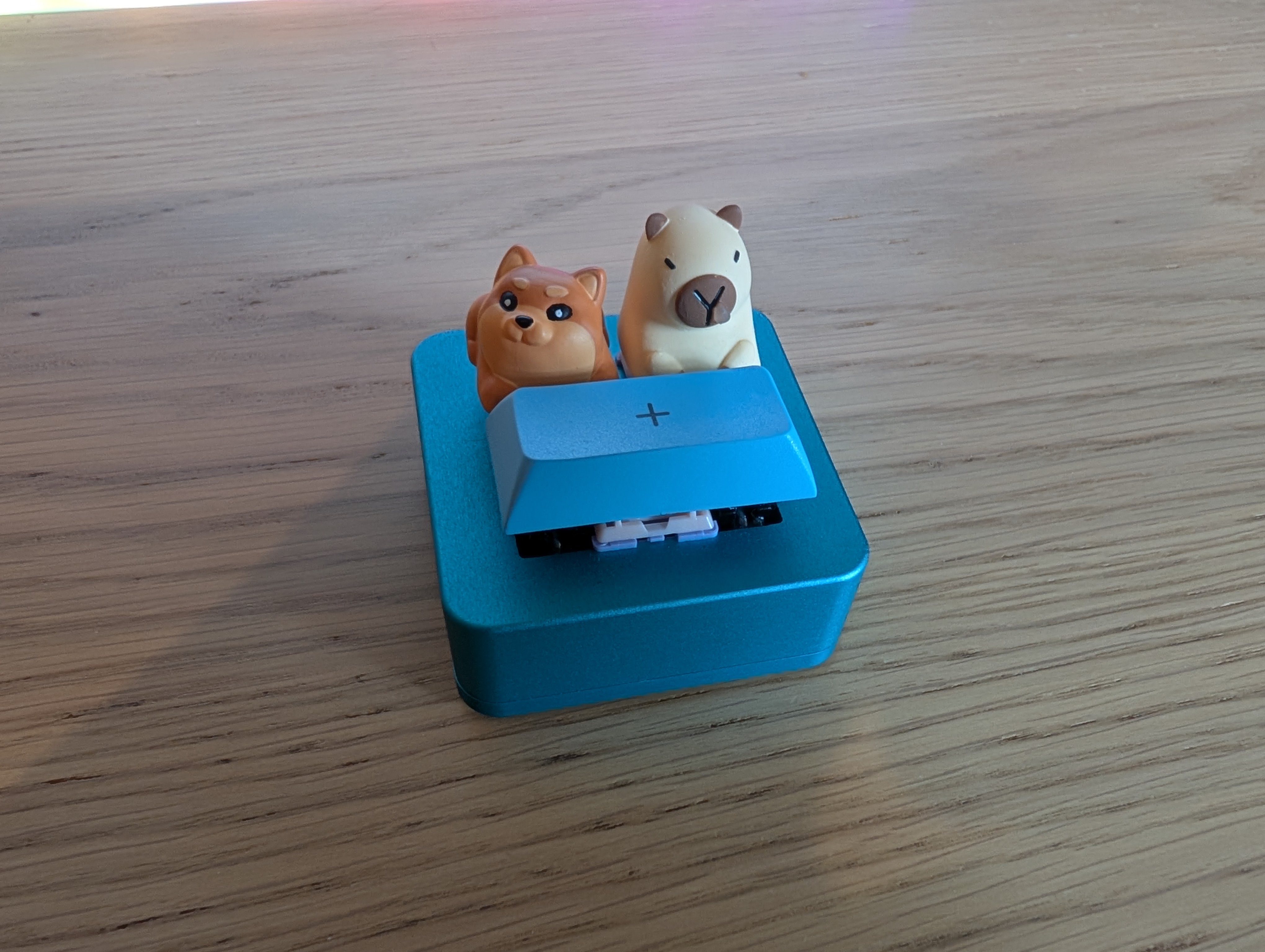
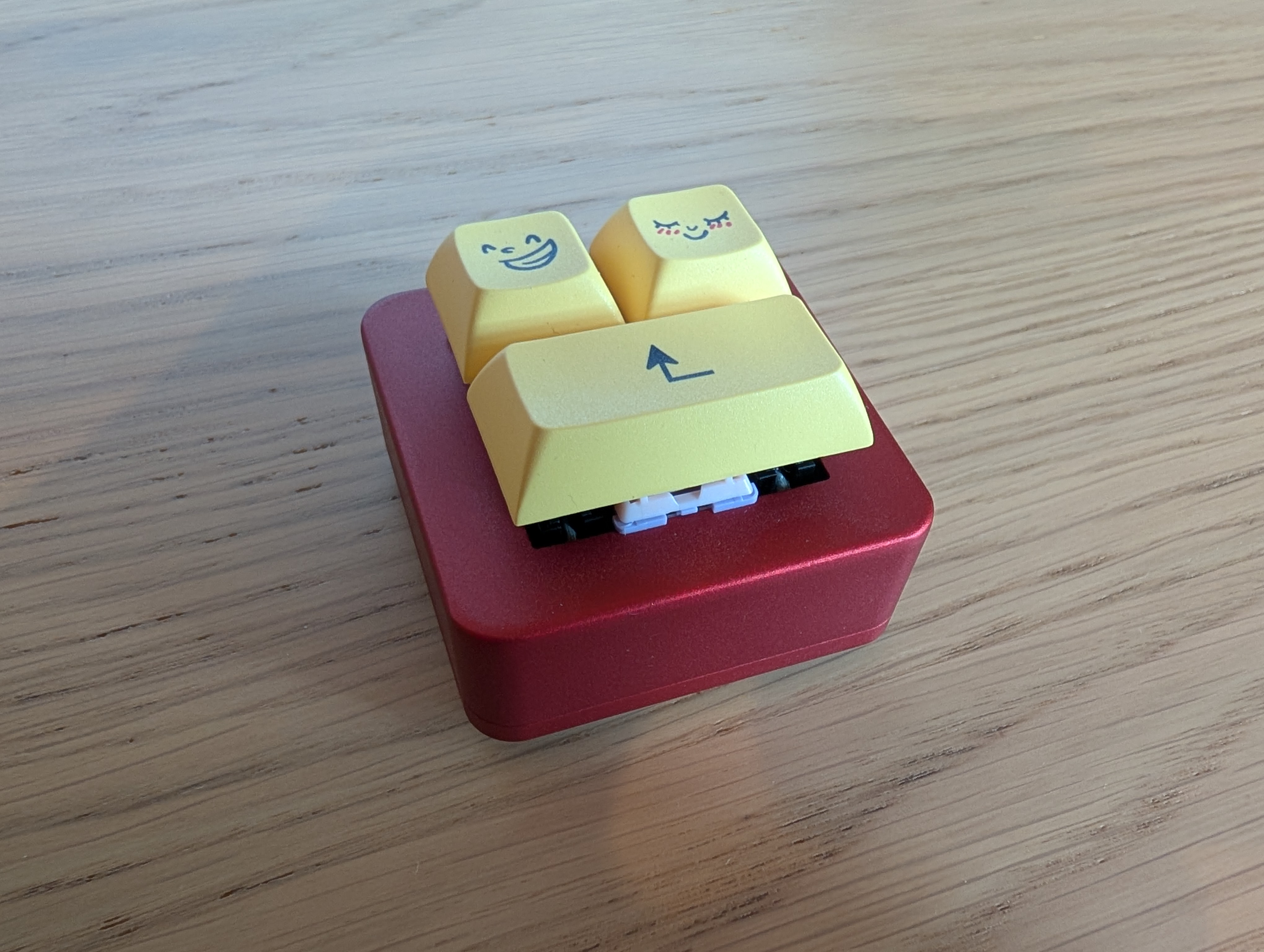
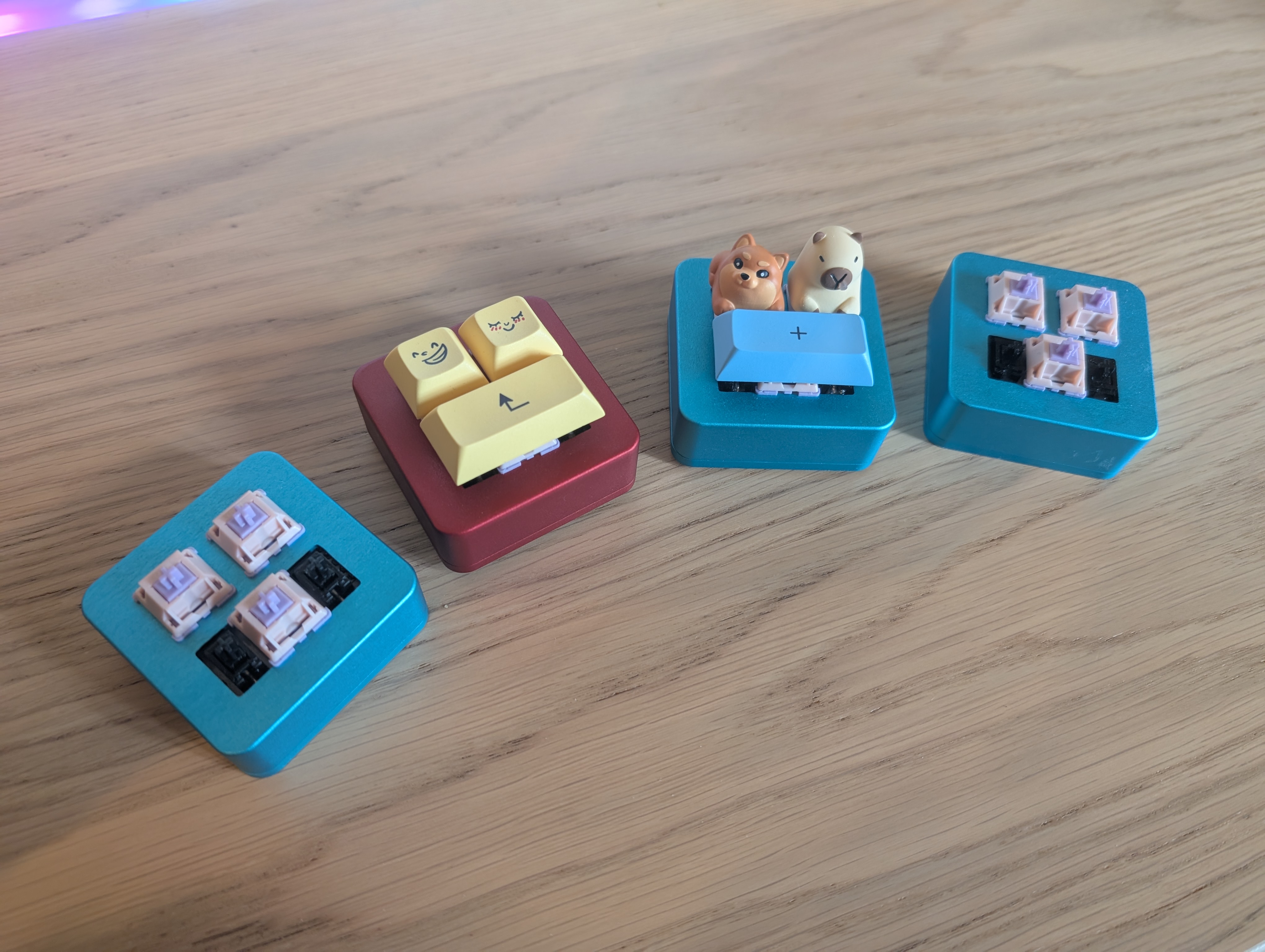
The gerbers are included in the repo in the kicad directory. You can simply upload the gerbers to a service like JLCPCB.
Not that the entire Kicad project is included so you can also regenerate the gerbers with different settings if needed or adjust the PCB.
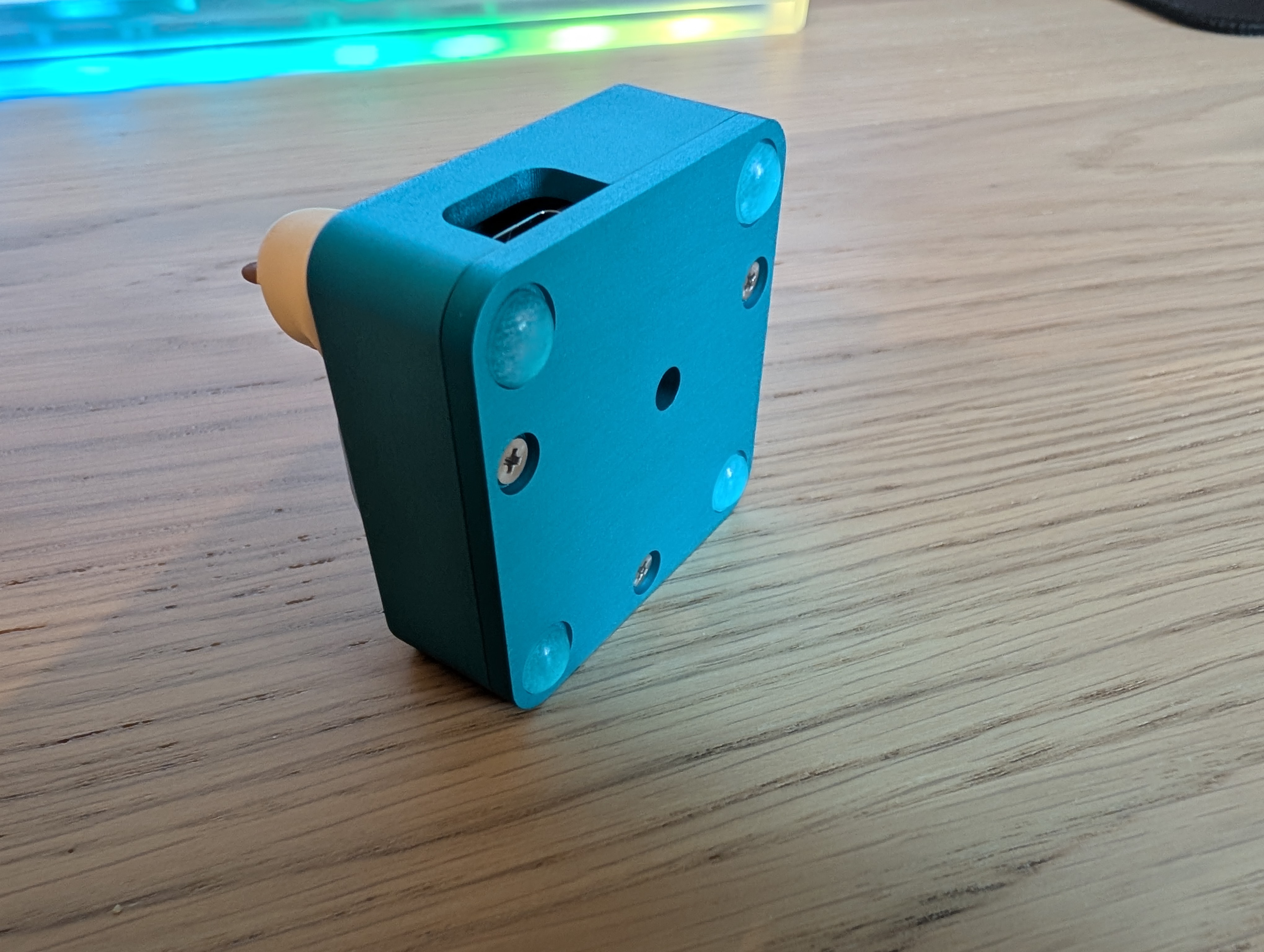
The case was CNC'd out of aluminium (again by JLCPCB). The case is made up of two (top, bottom) parts.
The two parts are held together using 3 M2.5 screws. There is also a drawing showing the exact placement of the threads.
It might be possible to 3D print the case, but the screw threads might make it difficult.
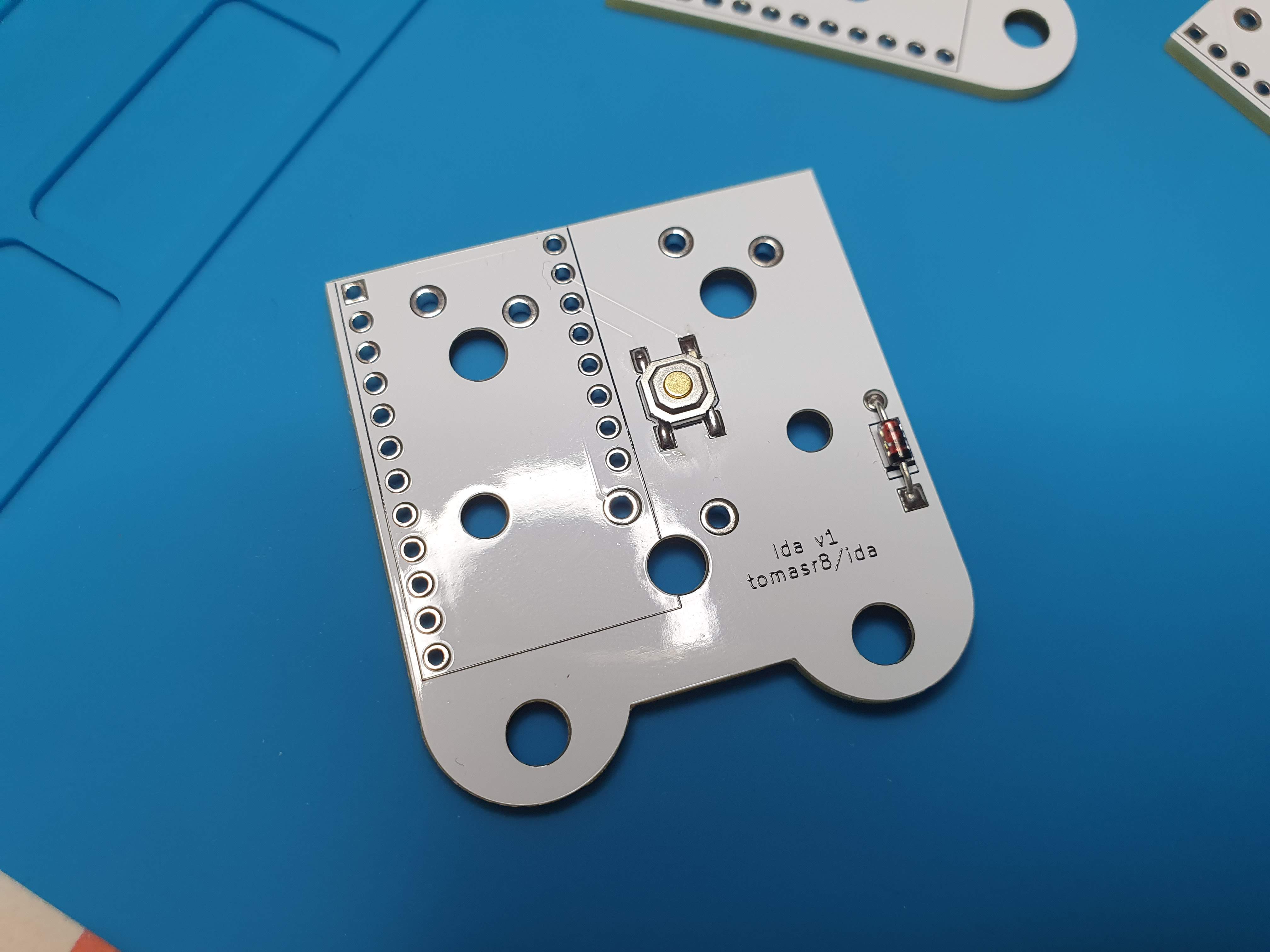
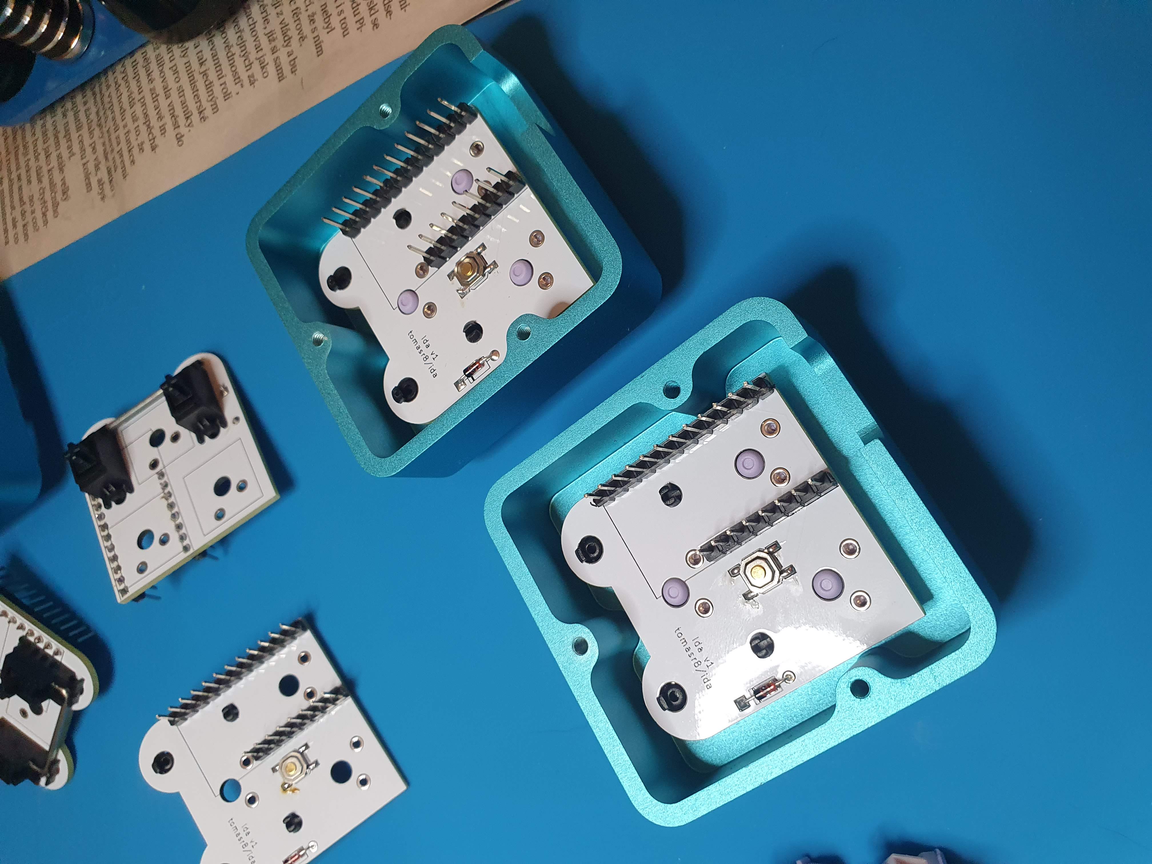
Step 1: Solder the reset switch and the diode:
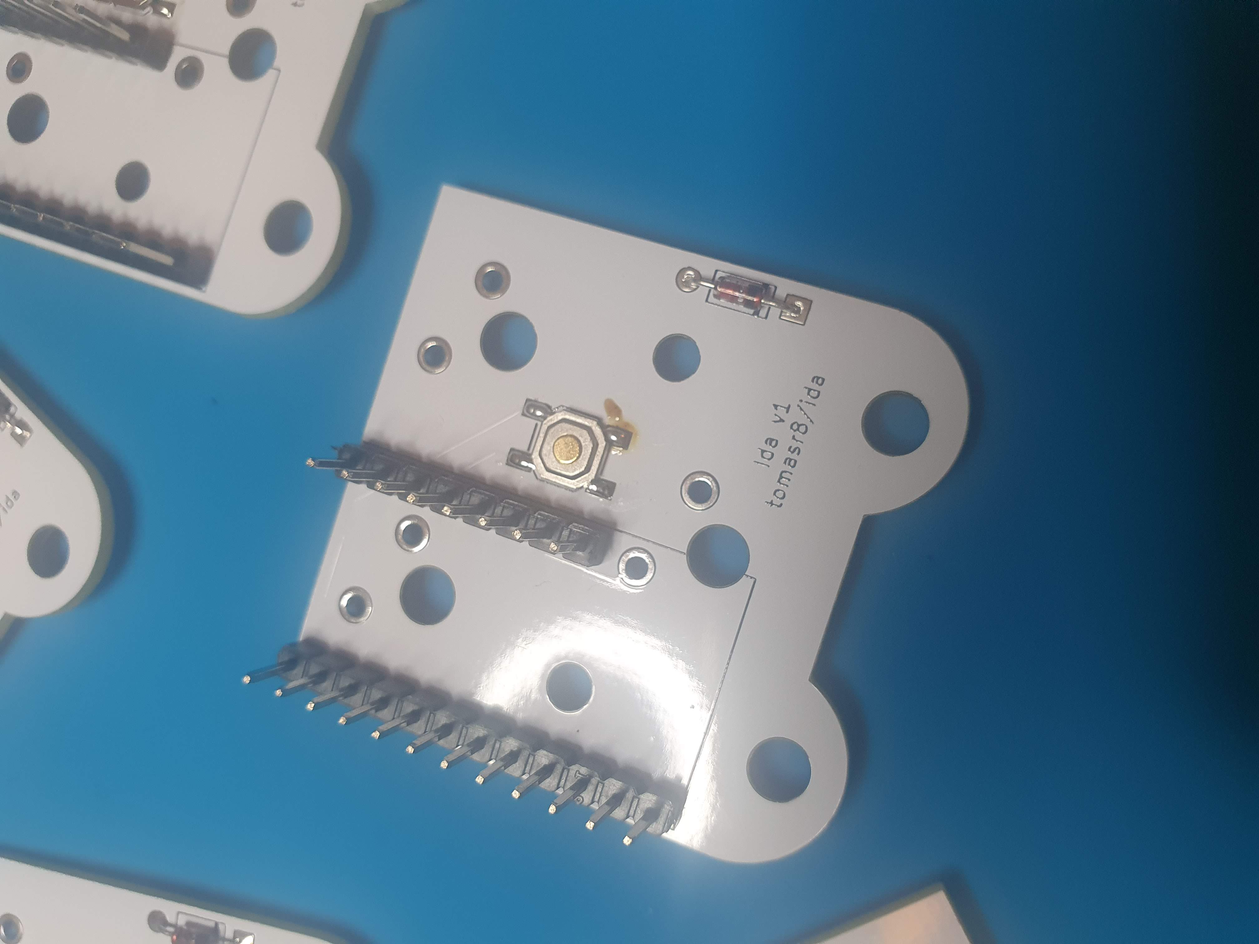
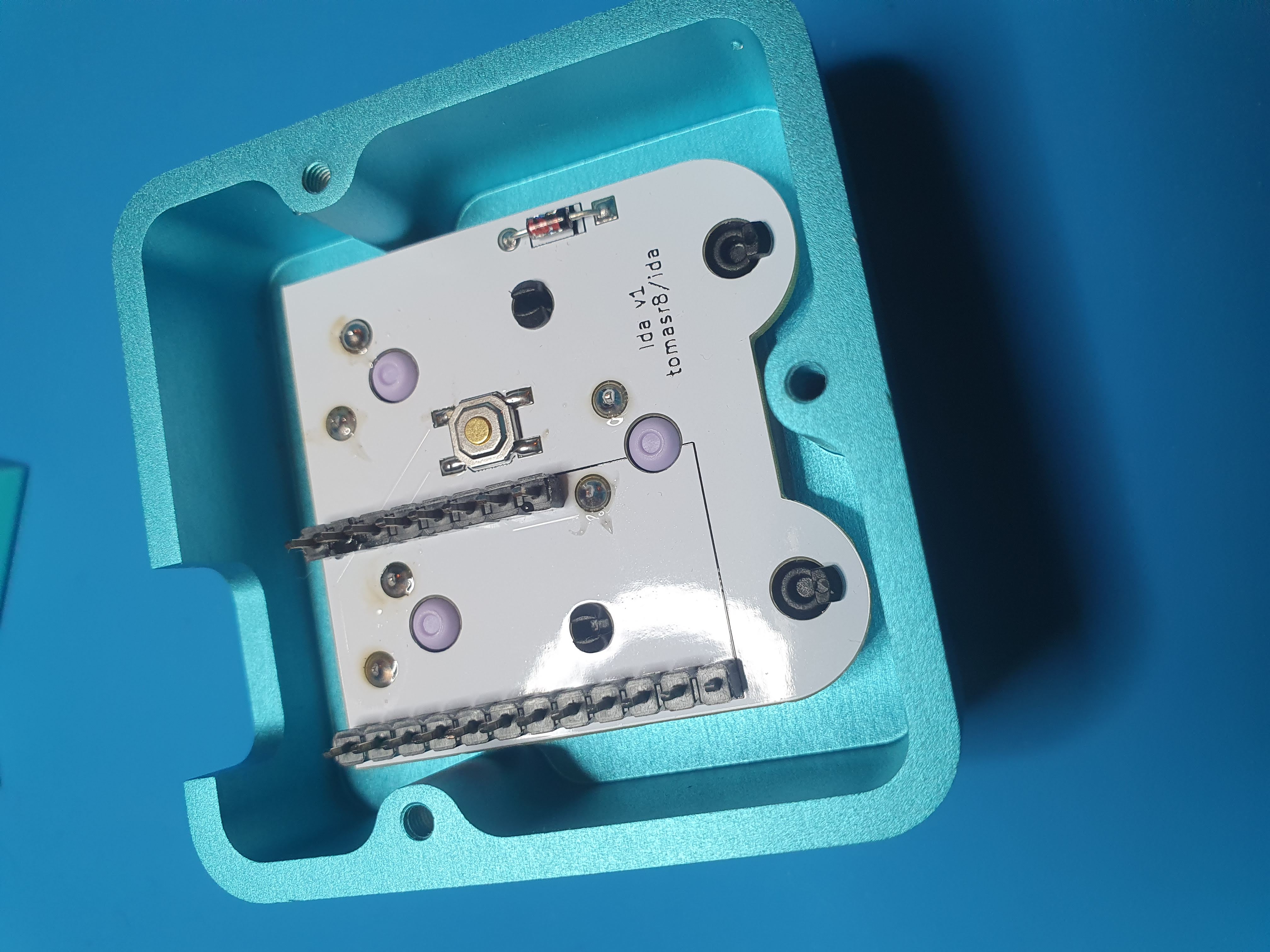
Step 2: Solder the pin headers:
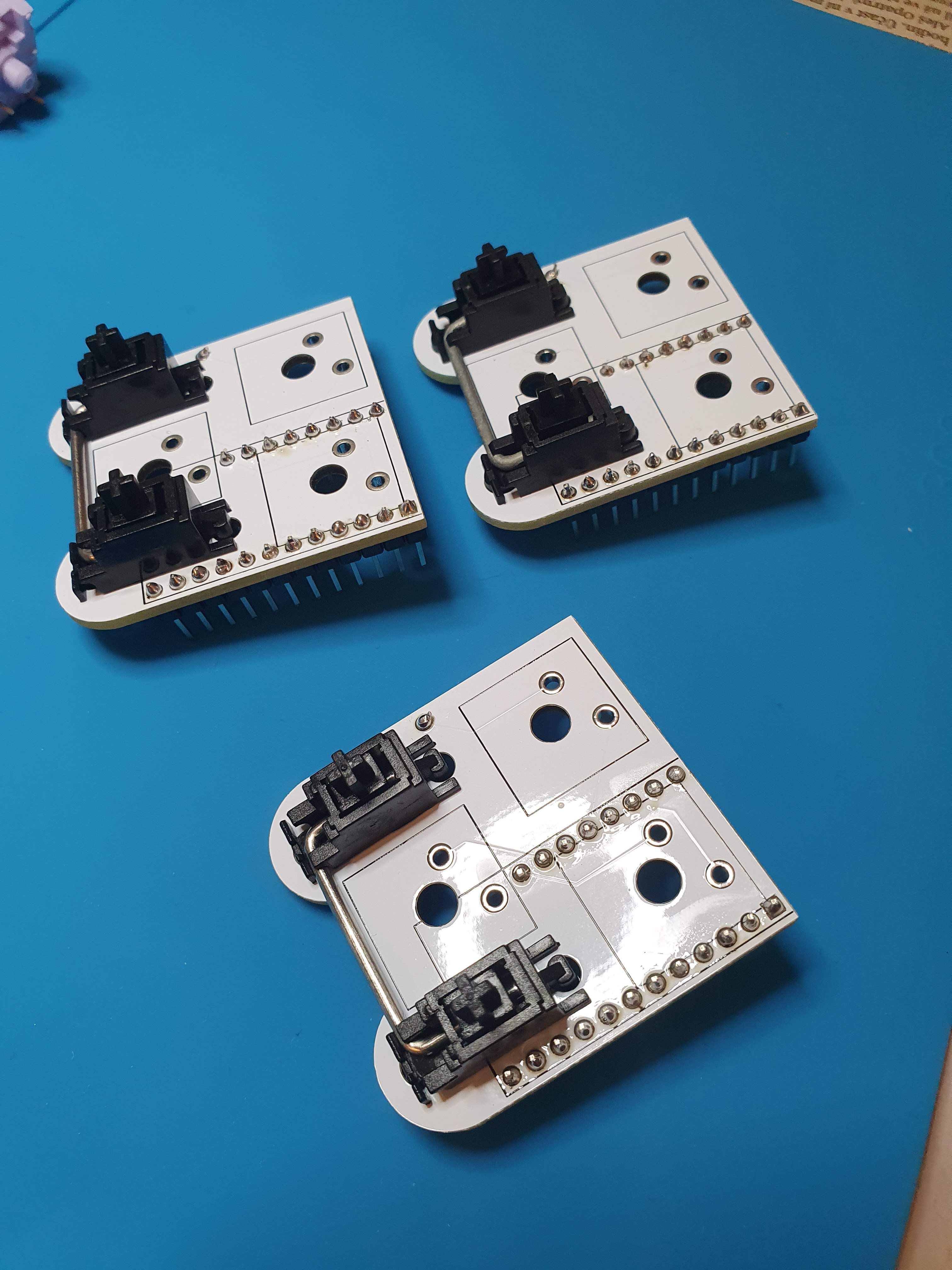
Step 3: Place the stabilizers:
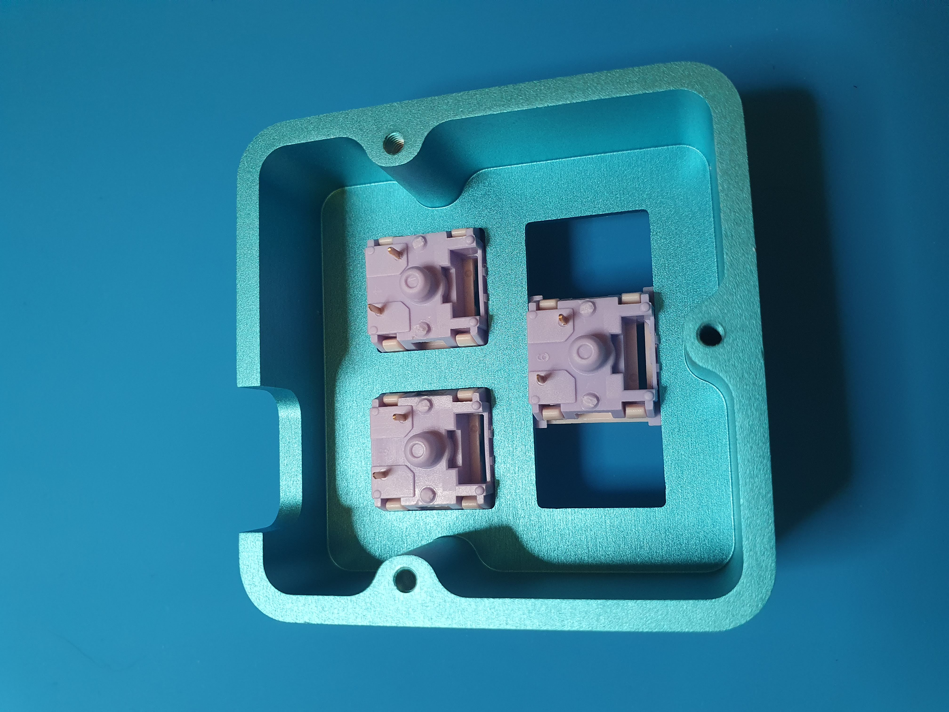
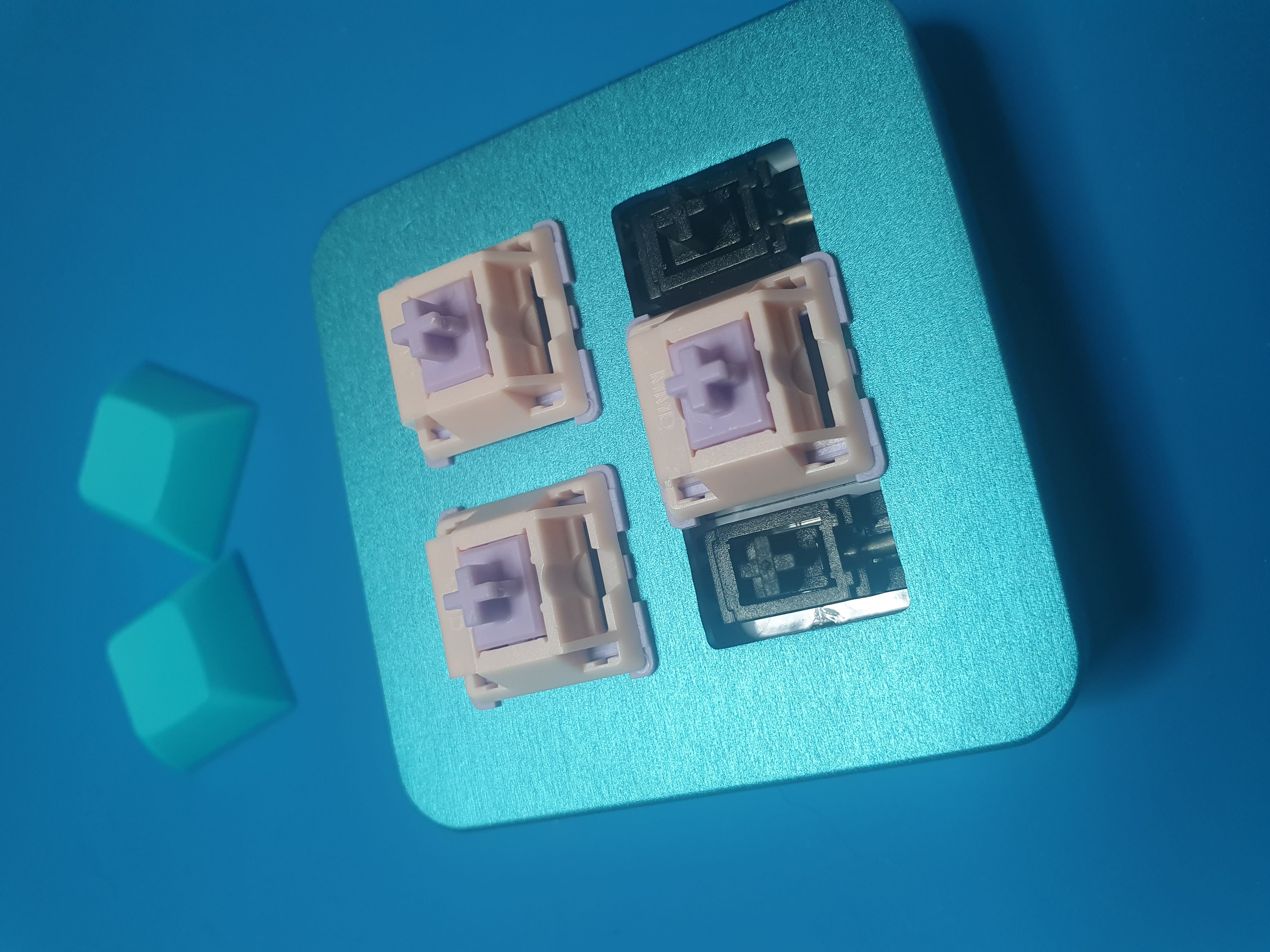
Step 4: Place switches in the enclosure:
Step 5: Place the PCB inside the enclosure and solder the switches:
Step 6: Place and solder the Pro Micro:
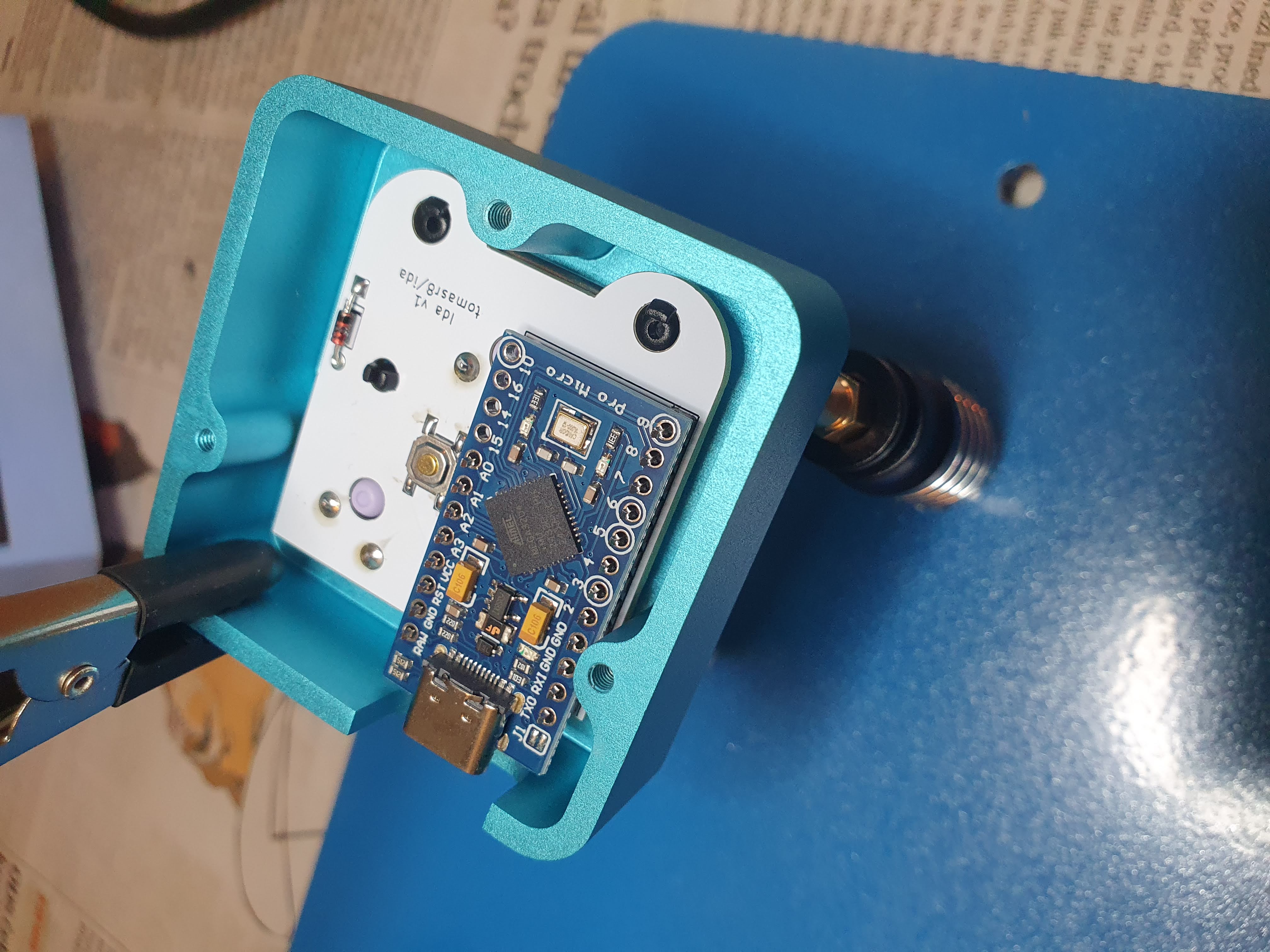
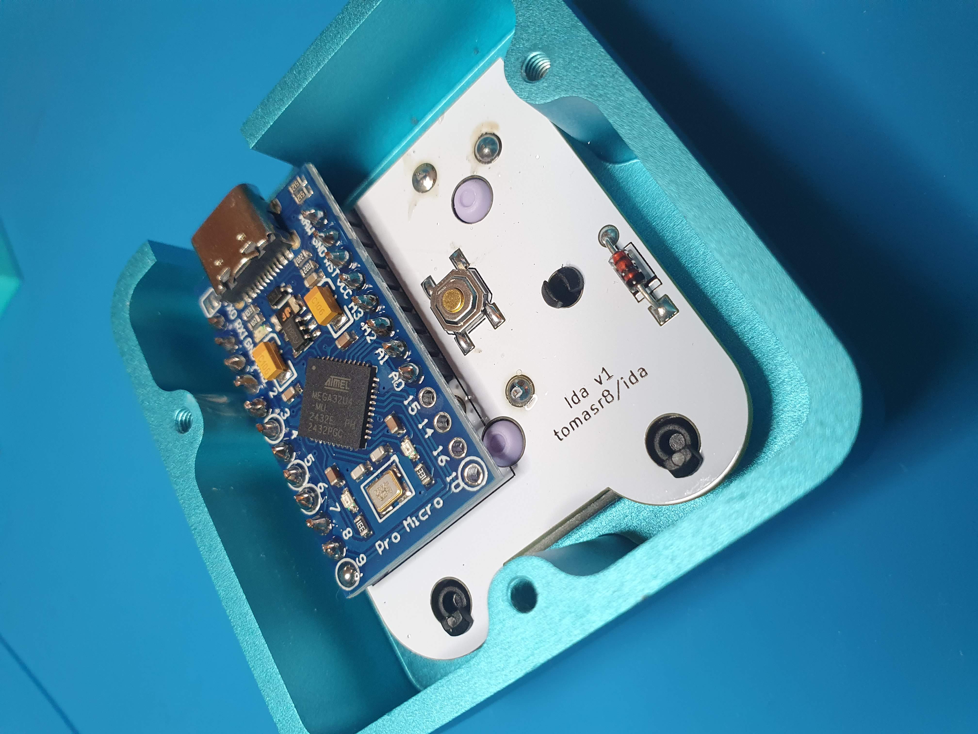
Step 7: Screw the bottom part of the case:
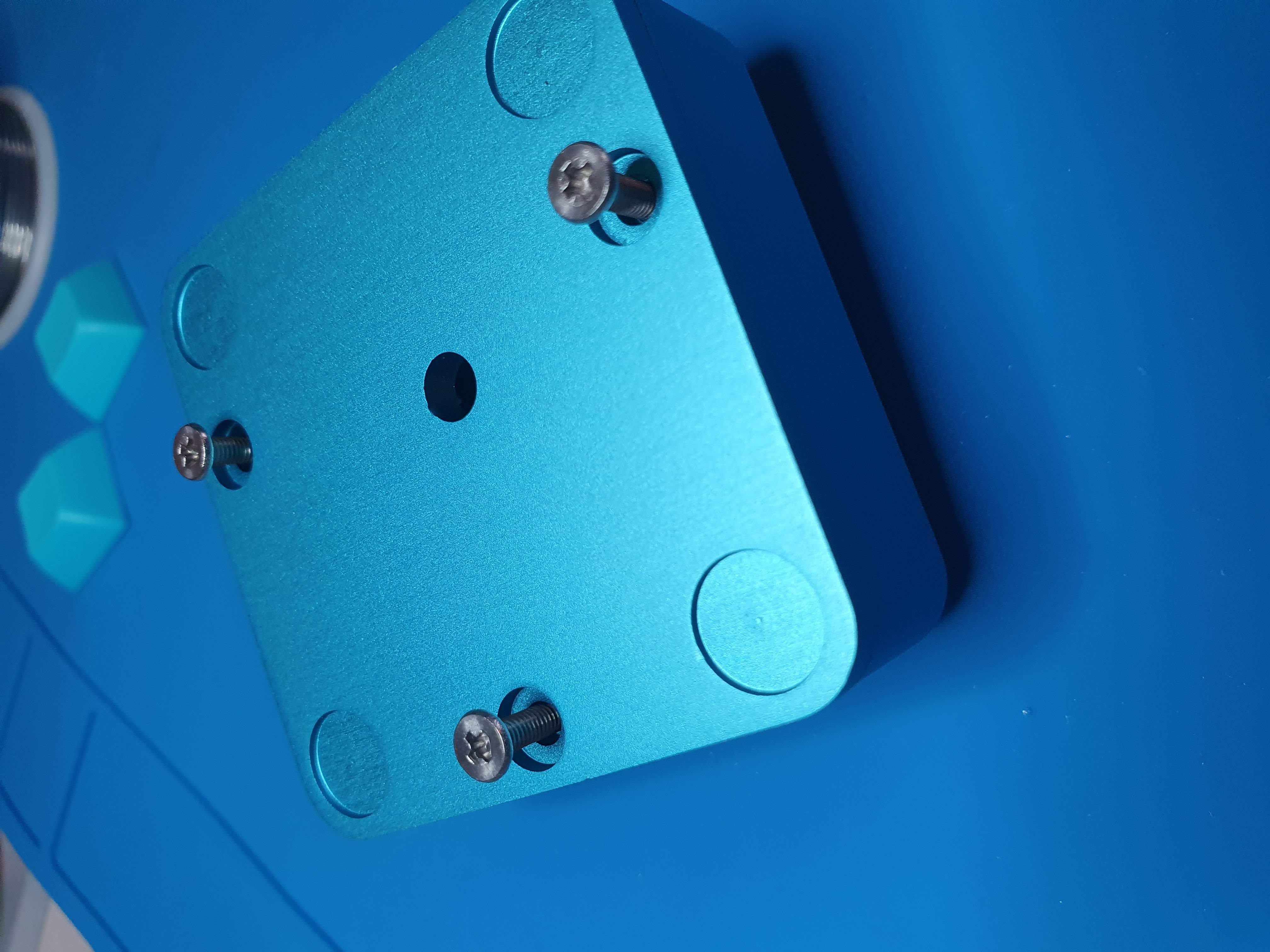
Done!
I use QMK for programming the macropad. You can use my fork of QMK to change the keymap: https://github.com/tomasr8/qmk_firmware/tree/ida/keyboards/ida
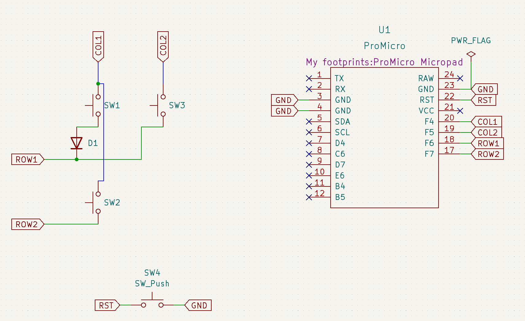
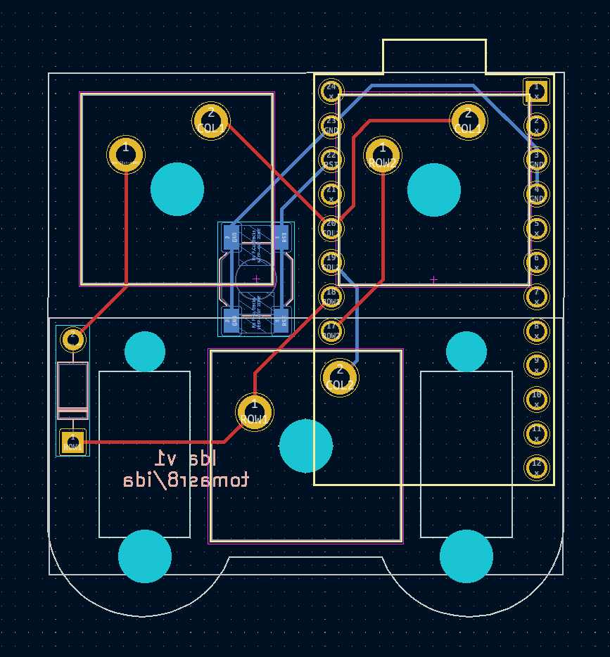
| Qty | Value | Footprint | References |
|---|---|---|---|
| 2 | SW_Push | My footprints:SW_Cherry_MX_Plate | SW1, SW2 |
| 1 | 1N4148 | Diode_THT:D_DO-35_SOD27_P7.62mm_Horizontal | D1 |
| 1 | ProMicro | My footprints:ProMicro Micropad | U1 |
| 1 | SW_Push | My footprints:SW_Cherry_MX_Plate_2.00u | SW3 |
| 1 | SW_Push | Button_Switch_SMD:SW_SPST_SKQG_WithoutStem | SW4 |
The 6 most common of 7 parts.
byrantech/laptop
anyon_e, a highly integrated, high end, open source laptop. Attempt the impossible.


AxxAxx/AxxSolder
STM32 Based soldering station for JBC cartridges, 9-24 VDC and USB-PD power


jamro/tiny-engineer
A small desktop robot that brings an AI coding assistant to life, physically acting out when it reads files, thinks, writes code, and finishes work.

hoglet67/RGBtoHDMI
Bare-metal Raspberry Pi project that provides pixel-perfect sampling of Retro Computer RGB/YUV video and conversion to HDMI

It measures 38.3 × 40.4 mm and has 2 copper layers, 1.6 mm thick.
7 parts. The full list of its parts is on this page, with links to each part's symbol and footprint where PCBKit's library has them.
From the tomasr8/ida repository on GitHub, at the commit this page was made from: the board is kicad/micropad.kicad_pcb and its schematic kicad/micropad.kicad_sch. PCBKit opens the board in the browser, with nothing to install.
Its repository states no licence, so its author keeps all rights: ask tomasr8 before reusing the design.