4 layers62 × 22.2 mm
UPduino v3.0
tinyvision-ai-inc/UPduino-v3.0
UPduino 3.0: new 4 layer layout, various other improvements
116 parts365MIT
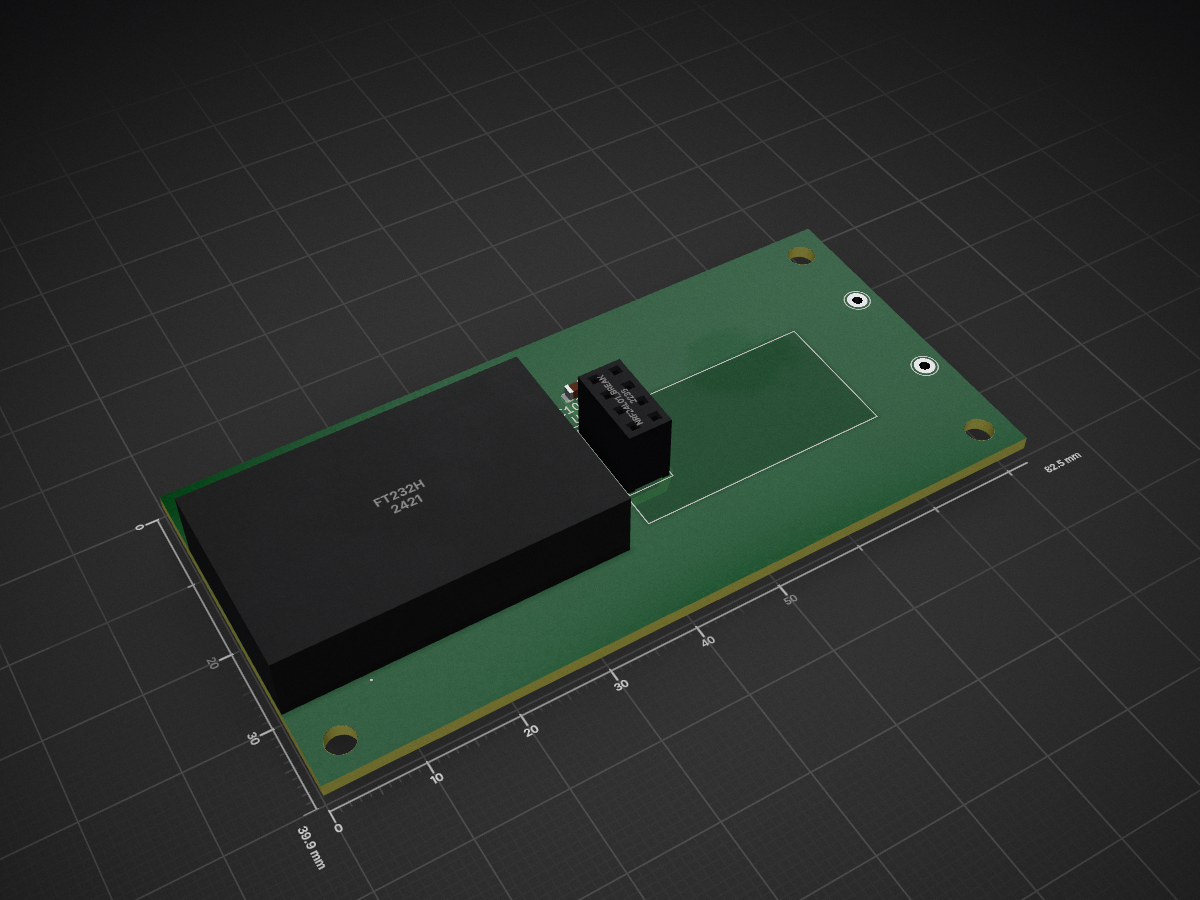
 tomapel721/Telemetry-Receiver
Telemetry system receiver designed for a Formula Student car
Telemetry Receiver is an open-source printed circuit board by tomapel721, from the tomapel721/Telemetry-Receiver repository on GitHub. It is a 2-layer board of 82.6 × 39.9 mm with 10 parts on 22 nets, routed with 37 tracks and 2 vias.
It is built around the FT232H. Its parts include 2 ICs and 1 capacitor.
The receiver part of telemetry system which was implemented inside a Formula Student EV.
Used QT Framework
Front-end: QML
Back-end: QT C++
In main directory, you can find 2 other folders:
Usage of the code can be hard to do, but in case you want to make your own racing car, here is the brief manual:
| Qty | Value | Footprint | References |
|---|---|---|---|
| 4 | MountingHole:MountingHole_3.2mm_M3_DIN965 | , , , | |
| 2 | Connector_Pin:Pin_D1.0mm_L10.0mm_LooseFit | , | |
| 1 | C | Capacitor_SMD:C_0805_2012Metric | C100nF1 |
| 1 | FT232H | Telemetry_receiver:AdafruitFT232HBreakout | U1 |
| 1 | LOGO | Loga_PolSl_Racing:Logo_Racing_5x5 | G*** |
| 1 | NRF24L01_Breakout | RF_Module:nRF24L01_Breakout | U2 |
tinyvision-ai-inc/UPduino-v3.0
UPduino 3.0: new 4 layer layout, various other improvements

efabless/caravel_board
This repo provides firmware examples, flash programming and diagnostic tools for testing Open MPW and chipIgnite projects using Caravel.

riktw/HUB75E_ICE40
SpinalHDL code to drive a 64*64 pixel HUB75E module with an ICE40


anthonydotmoe/68040pc
A general purpose computer platform for retrocomputing enthusiasts

It measures 82.6 × 39.9 mm and has 2 copper layers, 1.6 mm thick.
10 parts, built around the FT232H. The full list of its parts is on this page, with links to each part's symbol and footprint where PCBKit's library has them.
From the tomapel721/Telemetry-Receiver repository on GitHub, at the commit this page was made from: the board is Telemetry-Receiver/PCBDesign/Telemetry_receiver/Telemetry_receiver.kicad_pcb. PCBKit opens the board in the browser, with nothing to install.
Its repository states no licence, so its author keeps all rights: ask tomapel721 before reusing the design.