4 layers131.6 × 90 mm

 todbot/sketchingpad1
Capsense touch BLE pad for Sketching
Sketchingpad proto2 is an open-source printed circuit board by todbot, from the todbot/sketchingpad repository on GitHub, published under the GPL-3.0 licence. It is a 4-layer board of 158.4 × 66 mm with 84 parts on 73 nets, routed with 641 tracks and 91 vias.
It is built around the TS20, SK6812SIDE-A-S and AO3415A, with the HC-1.0-4PWT, S2B-PH-SM4-TB(LF)(SN) and TC-S3601-3.5-260G-F0.6 among its other parts. Its parts include 23 capacitors, 20 diodes, 7 resistors, 3 connectors and 2 ICs. It belongs with the keyboards and input and radio and wireless boards and the nRF52 and nRF5x boards of this library.


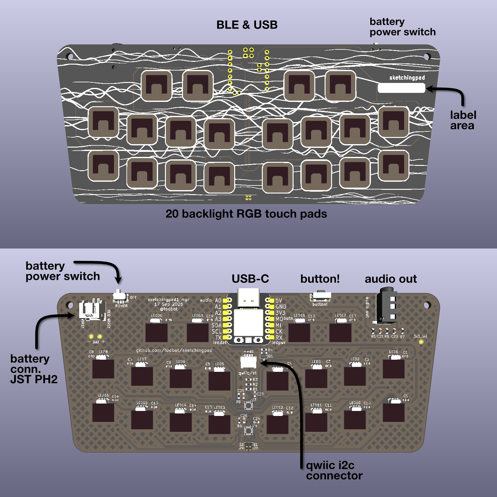
Install pre-built apps using the -| sketchingpad web flasher |-
Most of the apps are Arduino sketches, see arduino/README.md
for details on Arduino firmware options including: how to flash, how to build,
the touch layer, the BLE LED animation packet layer,
the power tiers, etc. Examples of what's available:
sketchingpad_party -- record an animation, broadcast it, with power tierssketchingpad_midi_simple -- USB + BLE MIDI controllersketchingpad_gamepad -- USB + BLE HID gamepad, two sticks, D-pad, 8 buttonsble_keyboard -- BLE HID keyboard, with power tiersble_keyboard_simple -- BLE HID keyboard, no power mgmthwtest_leds -- chases one pixel around the 20 LEDshwtest_touch_lowpower -- pad -> LED, fading, plus three power tiers, no BLEhwtest_touch -- pad -> LED with a fading trail, no BLEmore sketches in arduino/README.md.
arduino/tests/ holds host-native tests for the dependency-free
headers: cd arduino/tests && make run.
CircuitPython is much easier to work with, but can't get the same low-power modes available in Arduino.
Each program directory holds the files to copy to the CIRCUITPY root.
sketchingpad_midi_simple -- USB + BLE MIDI controllerble_keyboard_lowpower -- low-power BLE HID keyboard,
two power tiers rather than the Arduino sketch's three.These work on both versions of the board (TS20 & MPR121). Other programs listed in circuitpython/README.md
Host tests for the touch layer, needing no board and no install:
cd circuitpython/tests && make run. They also pin the pad tables in
touch.py against arduino/shared/touch_map.h, which nothing else does.
Libraries come from circup; see circuitpython/requirements.txt.
See circuitpython/notes-lowpower.md for why only two power tiers and not three.
docs/hardware-notes.md is the board side: both touch chips, their pad
numbering, their INT lines, and the board changes the firmware assumes.
docs/ also holds low-power-notes.md and the touch-chip datasheets.
The goal was to create a small 20 captouch pad keyboard-like board that let people in the same room share color patterns they "draw" on the pads, wirelessly, but then also could be something useful after the Sketching conference. Also desired was that the whole PCB being low-complexity and inexpensive, using JLC SMD PCBA capabilities and light hand-soldering.
The design points then:
Decisions:
MCU: XIAO NRF52840 - BLE and built-in LiPo charging in 1" sq package. Runner up: NRF52840 SuperMini (nice!nano clones), but suspect build quality. By going with XIAO/QTPy-format boards, other similar boards could be used, at the expense of the battery connections (which are in a non-standard location) for USB-only uses.
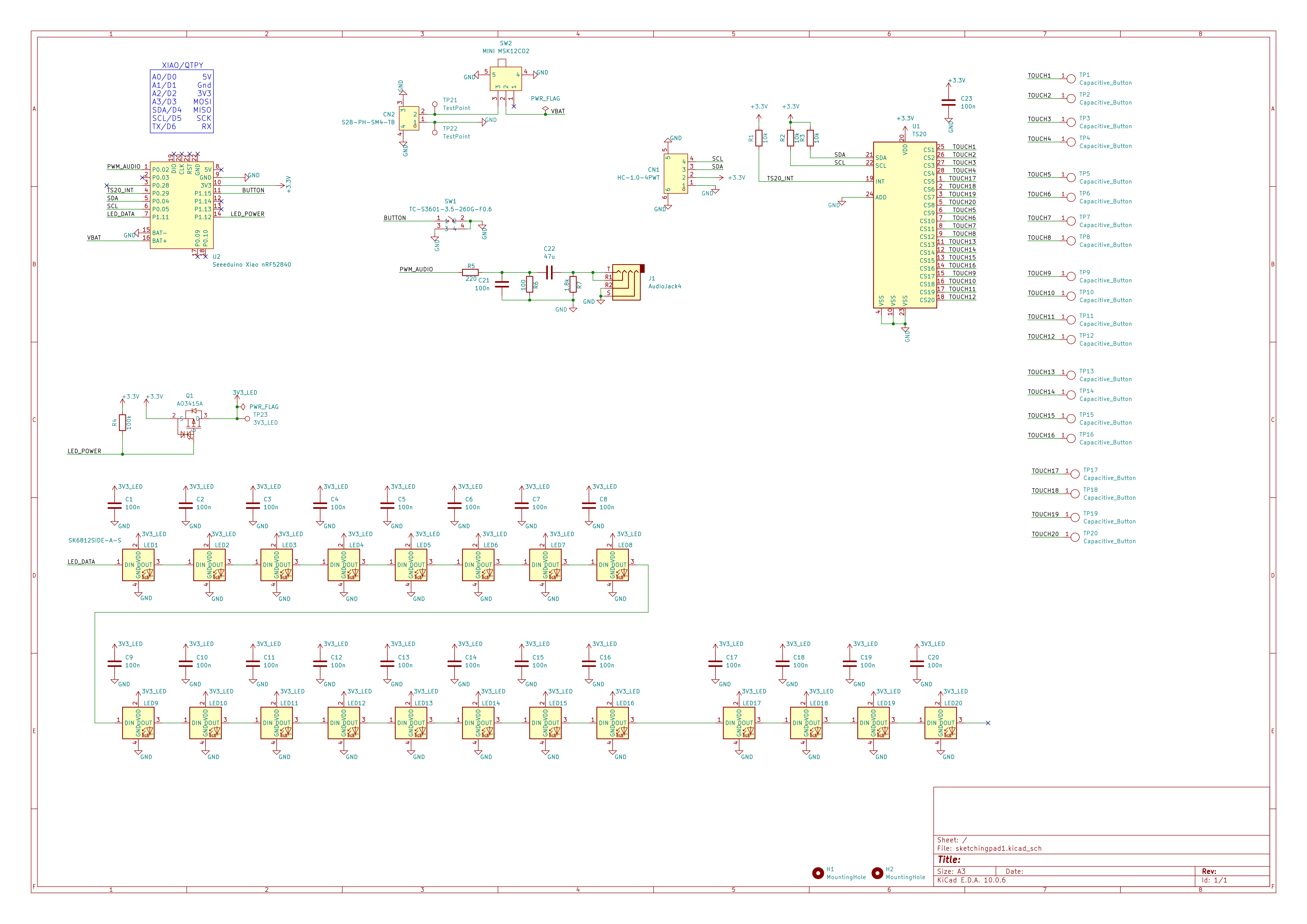
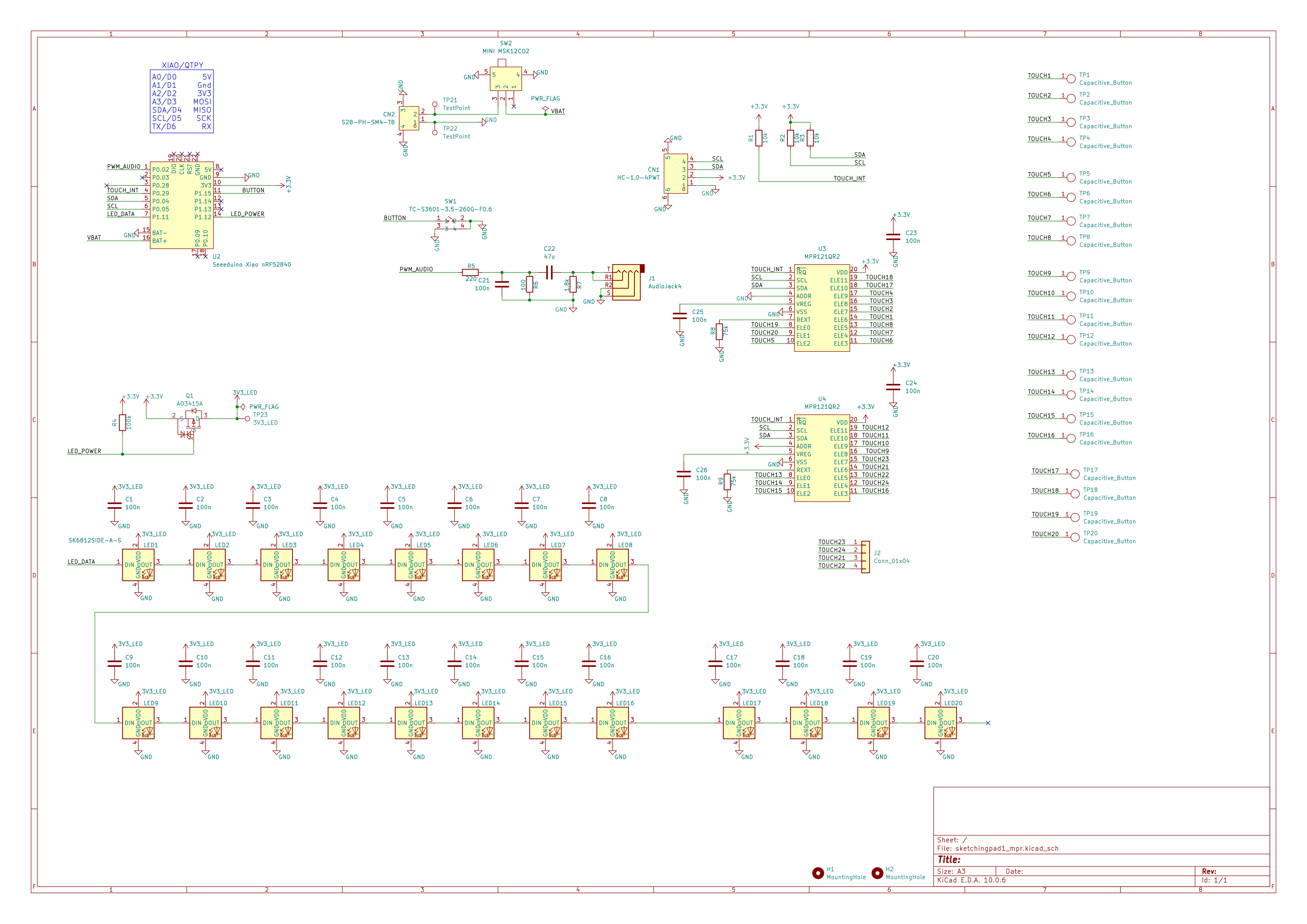
Touch chip: TS20 - cheap on LCSC and was always in stock, except during final production, so a quick switch to 2x MPR121. Both had 100 uA idle current and less in sleep mode but don't use sleep mode yet.
LEDs: SK6812-SIDE-A to backlight the touchpads. Backlight through PCB costs power, using Neopixel-like LEDs costs power (but these are static 0.25mA/LED). Using Neopixel-like LEDs on a battery-conscious design is foolish, but after spending weeks attempting to route an IS31FL3731 RGB design, I punted. The LEDs do at least have a PFET gating the power so we can save 5mA when not actively driving the LEDs.
Battery: LiPo 3.7V w/ JST 2.0 mm connector (RC standard, not adafruit standard), using LiPo charger built-in to XIAO NRF52840. Turns out AAA in a holder is very tall! I want this project to be flat. A small 3d-printable JST 2mm removal tool is really handy.
As seen in the photos, there is a simple 3d-printable enclosure. It's fast to print and you can snap the PCB in to quickly get started, or use M2.5 screws and nuts to secure the PCB more permanently.
Battery note: if you have a battery, attach the it with double-sided tape to the PCB and install the combined assembly in the case.
Installation into case: The snaps are on the top and the bottom.
To fit the PCB, secure it under the lower snap first,
then rotate the PCB down until it snaps with the top snaps.
Removal of the case: To remove the PCB from the case, carefully pry the top of the PCB away, working slowly on each side. Use the cutout holes for the button and audio jack as a place to start.
See the Demos section below for a video of installation & removal.
The sketchingpad1 and sketchingpad1_mpr1 boards have the same pinout:
| Signal | XIAO pin | Notes |
|---|---|---|
PWM_AUDIO | D0 / A0 | to audio jack via RC filter |
BUTTON | D10/MOSI | SW1 to GND, internal pull-up |
TOUCH_INT | D3 / A3 | open collector, R1 pulls up |
SDA | D4 | Wire default |
SCL | D5 | Wire default |
LED_DAT | D6 / TX | Neopixel data |
LED_POWER | D7 / RX | PFET gate, LOW = LED rail on |
Unused pins: D1 / A1, D8 / SCK, D9 / MISO.
Note for battery power, you need to solder the BAT+ / BAT- pins on the bottom of the XIAO to the corresponding pads on the PCB.
There are two versions of the board:
sketchingpad1 - uses one TS20 touch chipsketchingpad1_mpr - uses two MPR121 touch chipsKiCad source files available in the "schematics" directory.
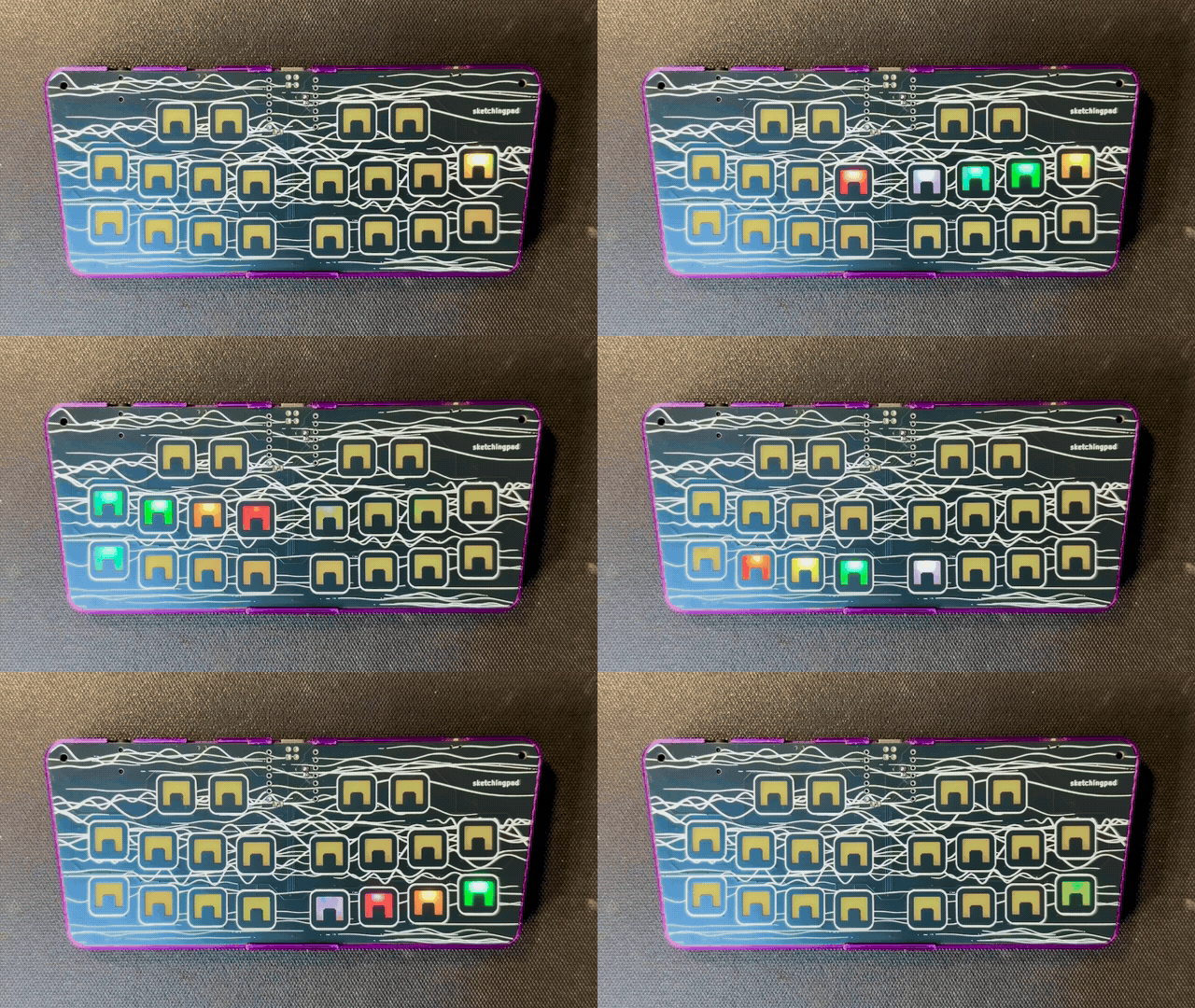
Sketch a color pattern with your fingers on the bottom 16 pads. After 1.5s of pause, it transmits that pattern to all other sketchingpad1_party boards. Top 4 pads select which colors. Each pad toggles between two colors.
https://github.com/user-attachments/assets/d27a3079-bf75-4f49-8079-a613aa76e5e4
How to install & remove the case.
https://github.com/user-attachments/assets/99311e4a-093e-42f9-914b-14518b83df6d
| Qty | Value | Footprint | References |
|---|---|---|---|
| 22 | 100n | Capacitor_SMD:C_0603_1608Metric | C1, C2, C3, C10, C11, C12, C13, C14, C15, C16, C17, C18, C19, C20, C21, C23 +6 |
| 20 | Capacitive_Button | todbot_stuff:Pad-Captouch-0.5in-backlitB | TP1, TP2, TP3, TP4, TP5, TP10, TP11, TP12, TP13, TP14, TP15, TP16, TP17, TP18, TP19, TP20 +4 |
| 20 | SK6812SIDE-A-S | todbot_stuff:LED-SMD_4P-L4.0-W1.6-L-todedits | LED1, LED2, LED3, LED4, LED5, LED10, LED11, LED12, LED13, LED14, LED15, LED16, LED17, LED18, LED19, LED20 +4 |
| 3 | 10k | Resistor_SMD:R_0603_1608Metric | R1, R2, R3 |
| 2 | MountingHole | MountingHole:MountingHole_2.5mm | H1, H2 |
| 2 | TestPoint | TestPoint:TestPoint_Pad_D1.5mm | TP21, TP22 |
| 1 | 1.8k | Resistor_SMD:R_0603_1608Metric | R7 |
| 1 | 100 | Resistor_SMD:R_0603_1608Metric | R6 |
| 1 | 100k | Resistor_SMD:R_0603_1608Metric | R4 |
| 1 | 220 | Resistor_SMD:R_0603_1608Metric | R5 |
| 1 | 3V3_LED | TestPoint:TestPoint_Pad_D1.5mm | TP23 |
| 1 | 47u | Capacitor_SMD:C_0603_1608Metric | C22 |
| 1 | AO3415A | easyeda2kicad:SOT-23-3_L2.9-W1.6-P1.90-LS2.8-BR | Q1 |
| 1 | AudioJack4 | todbot_stuff:Jack_3.5mm_PJ320D_Horizontal | J1 |
| 1 | HC-1.0-4PWT | easyeda2kicad:CONN-SMD_4P-P1.00_HCTL_HC-1.0-4PWT | CN1 |
| 1 | LOGO | LOGO | G*** |
| 1 | MINI MSK12CO2 | easyeda2kicad:SW-SMD_MSK12CO2 | SW2 |
| 1 | S2B-PH-SM4-TB | easyeda2kicad:CONN-SMD_P2.00_S2B-PH-SM4-TB-LF-SN | CN2 |
| 1 | Seeeduino Xiao nRF52840 | todbot_stuff:Xiao_nRF52840_ACH-todedit | U2 |
| 1 | TC-S3601-3.5-260G-F0.6 | easyeda2kicad:SW-SMD_TC-S3601-3.5-260G-F0.6 | SW1 |
| 1 | TS20 | Package_SO:TSSOP-28_4.4x9.7mm_P0.65mm | U1 |


AEFeinstein/Super-2023-Swadge-HW
Swadge devkit for an ESP32-S2 with all the bells and whistles


alex31/smartprobe
firmware and hardware for an autonomous five holes 3D pitot tube

cnlohr/cnhardware
My dumping grounds for all my kicad projects and random hardware bringup.

todbot/picotouch_drumcard
Card-sized drum synth / sequencer with MIDI In/Out


It measures 158.4 × 66 mm and has 4 copper layers, 1.6 mm thick.
84 parts, built around the TS20, SK6812SIDE-A-S, AO3415A and HC-1.0-4PWT. The full list of its parts is on this page, with links to each part's symbol and footprint where PCBKit's library has them.
From the todbot/sketchingpad repository on GitHub, at the commit this page was made from: the board is schematics/old/sketchingpad_proto2/sketchingpad_proto2.kicad_pcb and its schematic schematics/old/sketchingpad_idea1/leds.kicad_sch. PCBKit opens the board in the browser, with nothing to install.
Its repository publishes it under the GPL-3.0 licence: you may reuse it on that licence's terms (keep the author's notice, and for a copyleft licence share your changes alike).