Skip to the content
PCBKitNew board
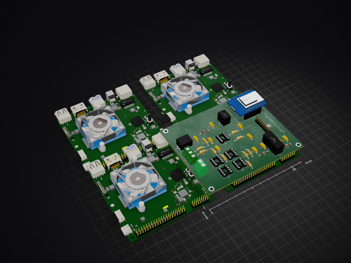
4 layers113 × 91.4 mmMFJLoopController, the printed circuit board in 3D

MFJLoopController

tmiw/MFJLoopController6

A ESP8266-based remote controller for MFJ magnetic loops.

Size
113 × 91.4 mm
Copper layers
4
Thickness
1.6 mm
Parts
40
Nets
55
Pads
144
Tracks, vias
112, 12
Pours
4
Routed
Yes
KiCad
KiCad 5 (file 20171130)
Created
12 Oct 2020
Updated
29 May 2021

Overview

MFJLoopController is an open-source printed circuit board by tmiw, from the tmiw/MFJLoopController repository on GitHub, published under the BSD-3-Clause licence. It is a 4-layer board of 113 × 91.4 mm with 40 parts on 55 nets, routed with 112 tracks and 12 vias.

It is built around the R-785.0-1.0, WEMOS D1 MINI and AD8032AN, with the LCC120 among its other parts. Its parts include 10 capacitors, 10 resistors, 8 ICs, 4 connectors and 3 inductors. It belongs with the ESP8266 boards of this library.

Main components

4

README

README.md

MFJLoopController

A ESP8266-based remote controller for MFJ magnetic loops.

Prerequisites

  • WEMOS D1 mini Lite development board (or clone). Example
  • Adafruit ADS1115 ADC
  • Arduino IDE with ESP boards and LittleFS data uploader tool installed
  • MFJ Bias Tee
  • H bridge circuit to produce +/- 12V. Initial tests done with LED based solid state relays linked together in series to reduce required pin count to 2 (one for each direction).
  • Isolated power supply (e.g. NOT connected to radio's ground). This Mouser project seems to work reasonably well in initial testing to permit sharing 12V power supply with rest of shack (see datasheets for the TMR 9-1212 for required support circuitry to reduce possible RFI).
  • Soon: SWR bridge capable of reading 100W and providing 3.3V max analog signals to the ADS1115 (possible option)

Setup

  1. Set configuration options (pins, Wi-Fi info, etc.) in config.h.
  2. Build and upload software using Arduino IDE to device. Note: the initial upload must be done using USB or UART; subsequent uploads can be done OTA.
  3. Upload filesystem using Tools > ESP8266 LittleFS Data Upload in the Arduino IDE.

Usage

By default, the software uses DHCP to get an IP address. Simply go to its assigned IP address on port 80 in a Web browser and click on the desired tuning direction buttons; releasing the associated button results in tuning stop. Note that you're looking for maximum signal/noise for the initial pass at tuning; the eventual auto-tune feature will perform fine tuning for minimal SWR.

To Do

  • Auto-tuning
  • SSL support?
  • PCB combining all hardware and eliminating loose wires

License

BSD 3-clause (TBD)
Parts

40
QtyValueFootprintReferences
4LCC120Package_DIP:DIP-8_W7.62mm_SocketU5, U6, U7, U8
4MountingHole_PadMountingHole:MountingHole_3.2mm_M3_DIN965_Pad_TopBottomH1, H2, H3, H4
2100Resistor_THT:R_Axial_DIN0207_L6.3mm_D2.5mm_P10.16mm_HorizontalR7, R8
21000Resistor_THT:R_Axial_DIN0207_L6.3mm_D2.5mm_P10.16mm_HorizontalR9, R10
2150Resistor_THT:R_Axial_DIN0207_L6.3mm_D2.5mm_P10.16mm_HorizontalR5, R6
218KResistor_THT:R_Axial_DIN0207_L6.3mm_D2.5mm_P10.16mm_HorizontalR3, R4
22.2uFCapacitor_THT:C_Axial_L5.1mm_D3.1mm_P7.50mm_HorizontalC6, C7
222KResistor_THT:R_Axial_DIN0207_L6.3mm_D2.5mm_P10.16mm_HorizontalR1, R2
222uF 25VCapacitor_THT:C_Axial_L5.1mm_D3.1mm_P7.50mm_HorizontalC4, C8
2330nFCapacitor_THT:C_Axial_L5.1mm_D3.1mm_P7.50mm_HorizontalC9, C10
24.7nFCapacitor_THT:C_Axial_L5.1mm_D3.1mm_P7.50mm_HorizontalC2, C3
110uF 100VCapacitor_THT:C_Axial_L5.1mm_D3.1mm_P7.50mm_HorizontalC1
11mHInductor_THT:L_Axial_L5.3mm_D2.2mm_P10.16mm_Horizontal_Vishay_IM-1L3
12.2uF 100VCapacitor_THT:C_Axial_L5.1mm_D3.1mm_P7.50mm_HorizontalC5
14.7uHInductor_THT:L_Axial_L5.3mm_D2.2mm_P10.16mm_Horizontal_Vishay_IM-1L2
15.6uHInductor_THT:L_Axial_L5.3mm_D2.2mm_P10.16mm_Horizontal_Vishay_IM-1L1
1AD8032Package_DIP:DIP-8_W7.62mm_SocketU1
1Adafruit ADS1115Connector_PinHeader_2.54mm:PinHeader_1x10_P2.54mm_VerticalJ1
1Bias TeeTerminalBlock:TerminalBlock_bornier-2_P5.08mmJ2
1DC+12VConnector_BarrelJack:BarrelJack_CUI_PJ-063AH_Horizontal_CircularHolesJ4
1R-785.0-1.0Converter_DCDC:Converter_DCDC_RECOM_R-78E-0.5_THTU2
1SWR BridgeTerminalBlock:TerminalBlock_bornier-3_P5.08mmJ3
1TVN3-1212Converter_DCDC:Converter_DCDC_TRACO_TMR-xxxx_THTU3
1WeMos_D1_miniModule:WEMOS_D1_mini_lightU4

The 39 most common of 40 parts.

Questions

How big is the MFJLoopController PCB?

It measures 113 × 91.4 mm and has 4 copper layers, 1.6 mm thick.

What parts does the MFJLoopController use?

40 parts, built around the R-785.0-1.0, WEMOS D1 MINI, AD8032AN and LCC120. The full list of its parts is on this page, with links to each part's symbol and footprint where PCBKit's library has them.

Where can I download the MFJLoopController KiCad files?

From the tmiw/MFJLoopController repository on GitHub, at the commit this page was made from: the board is schematic/mfj-loop-controller.kicad_pcb. PCBKit opens the board in the browser, with nothing to install.

Can I use the MFJLoopController design in my own project?

Its repository publishes it under the BSD-3-Clause licence: you may reuse it on that licence's terms (keep the author's notice, and for a copyleft licence share your changes alike).

Similar boards

  • 6 layers117.3 × 75 mmProject Seminar SS2026, the printed circuit board in 3D

    Project Seminar SS2026

    girish-hk/6-Layered-Fuel-Cell-Monitoring-ESP32

    A six-layer fuel cell monitoring PCB designed in KiCad for accurate voltage and current measurement. The system integrates analog signal conditioning, precision ADC interfaces, and an ESP32-S3 microcontroller for data…

    123 parts
  • 2 layers95 × 50 mmGarage door driver, the printed circuit board in 3D

    Garage door driver

    mylife-home/mylife-home-devices

    MyLife Home devices

    32 partsGPL-3.0
  • 2 layers59.1 × 53.3 mmArdynoMon, the printed circuit board in 3D

    ArdynoMon

    TechColab/ArdynoMon

    Arduino shield for DIY dynos, engine monitoring & more.

    90 parts8GPL-3.0
  • 2 layers137.5 × 51 mmLark, the printed circuit board in 3D

    Lark

    tmshlvck/lark-hw

    Lark PCB

    112 parts3GPL-3.0
  • 2 layers160 × 160 mm6502-Computer, the printed circuit board in 3D

    6502-Computer

    Kampi/6502-Computer

    This is a W65C02 based microprocessor development and learning project.

    84 parts1
  • 2 layers86.4 × 76.2 mmDash Left, the printed circuit board in 3D

    Dash Left

    uvmaero/AERO_Boards

    All the Boards We Make

    45 parts1
  • 2 layers128.5 × 49.3 mmSupply Power, the printed circuit board in 3D

    Supply Power

    Alexandr-Filatov/Hydrogen-PCB-SupplyPower

    37 parts