
2 layers116.8 × 30 mm
Type d
google/mozc-devices
Circuit diagrams and firmware source code for Gboard DIY keyboards
14 parts3kApache-2.0

CircuitPython support for TI's TAC5XXX audio codecs
Tac5 is an open-source printed circuit board by timchinowsky, from the timchinowsky/tac5 repository on GitHub, published under the MIT licence. It is a 2-layer board of 17.3 × 30 mm with 14 parts on 24 nets, routed with 171 tracks and 41 vias.
Its parts include 7 capacitors, 4 resistors, 2 connectors and 1 IC. It belongs with the audio and music boards of this library.
This repo describes PCBs and rp2040/rp2350 CircuitPython support for TI's TAC5xxx audio codecs. This code depends on extensions to CircuitPython's rp2pio library found in https://github.com/adafruit/circuitpython/pull/9659.
pcm.py uses the rp2 PIO to implement a PCM interface to the TAC5 which supports arbitrary numbers of channels, word sizes, and sample rates.
tac5.py implements a TAC5 class which knows how to initialize the TAC5xxx over I2C, write to its DACs, and read from its ADCs.
If multiple TAC5xxx parts with different I2C addresses are present, they are assumed to be wired in parallel for multichannel operation and configured appropriately. In this mode, each chip uses one time slot in the DOUT signal and makes its DOUT Hi-Z at other times.
Chips are mounted on breakout boards. KiCad files for these boards are here. Schematic and layout look like this:
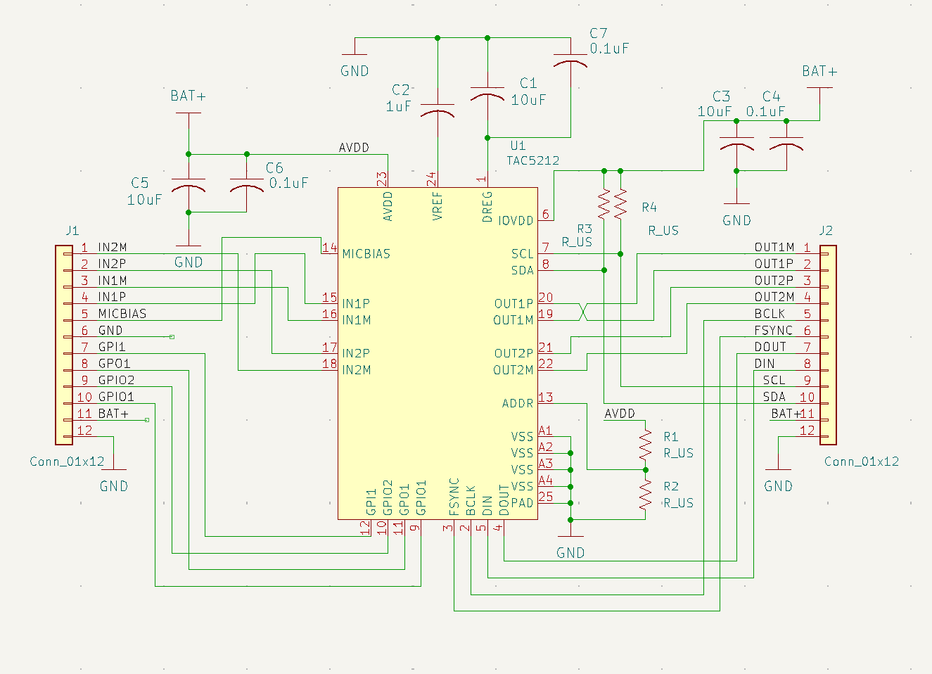
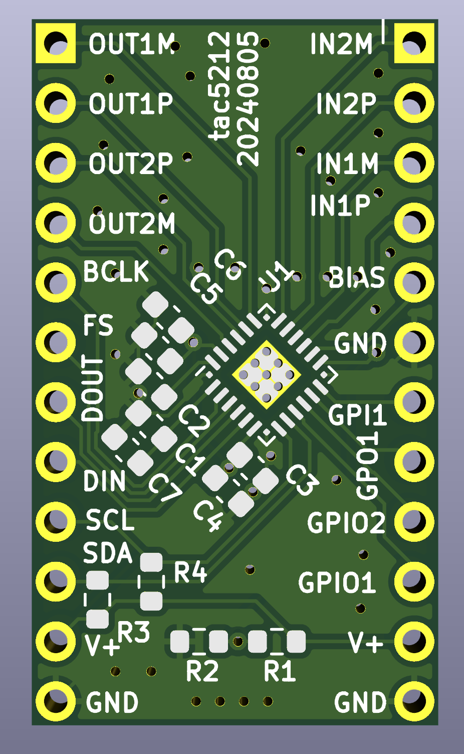
If you have speakers attached to the codecs, multi-track audio files stored on an SD card accessible to the rp2040 can be played on the codecs as follows:
Adafruit CircuitPython 9.1.0-beta.3-252-g10dfea4284-dirty on 2024-11-07; Adafruit Feather RP2040 with rp2040
>>> import tac5
>>> t=tac5.TAC5()
>>> t.play('/count_8ch_32bit_16000Hz.raw')
playing...
opening /count_8ch_32bit_16000Hz.raw ...
repeating...
repeating...
repeating...
...In this example, 4 TAC5212's are connected with BCLK, FSYNC, DOUT, DIN, SCL, and SDA in parallel, and on each chip, the differential DAC outputs are connected to the differential ADC inputs to provide test signals for the ADCs, i.e. OUT1P -> IN1P, OUT1M -> IN1M, OUT2P -> IN2P, OUT2M -> IN2M.
Adafruit CircuitPython 9.1.0-beta.3-76-g2f62612186-dirty on 2024-07-18; Adafruit Feather RP2040 with rp2040
>>>
>>> import tac5
>>> t = tac5.TAC5()
>>> t.play()
playing...
>>> t.record()
sample,record0,record1,record2,record3,record4,record5,record6,record7,
0,-1,-1,-1,-1,-21642,13829,-311,-14878,
1,22355,-20880,-14861,22749,-19762,8760,6829,-20253,
2,21608,-13819,-15930,23037,-17183,3144,13306,-22783,
3,18190,-3347,-16936,22962,-13994,-2666,18482,-22111,
4,10858,7951,-17876,22524,-10311,-8313,21849,-18332,
5,602,17291,-18745,21730,-6263,-13440,23074,-11979,
6,-8849,22352,-19541,20593,-1995,-17725,22040,-3945,
7,-17070,21881,-20257,19131,2341,-20896,18845,4634,
8,-21748,15993,-20896,17368,6597,-22754,13806,12577,
9,-22490,6149,-21452,15331,10620,-23182,7417,18743,
...(115 more lines)
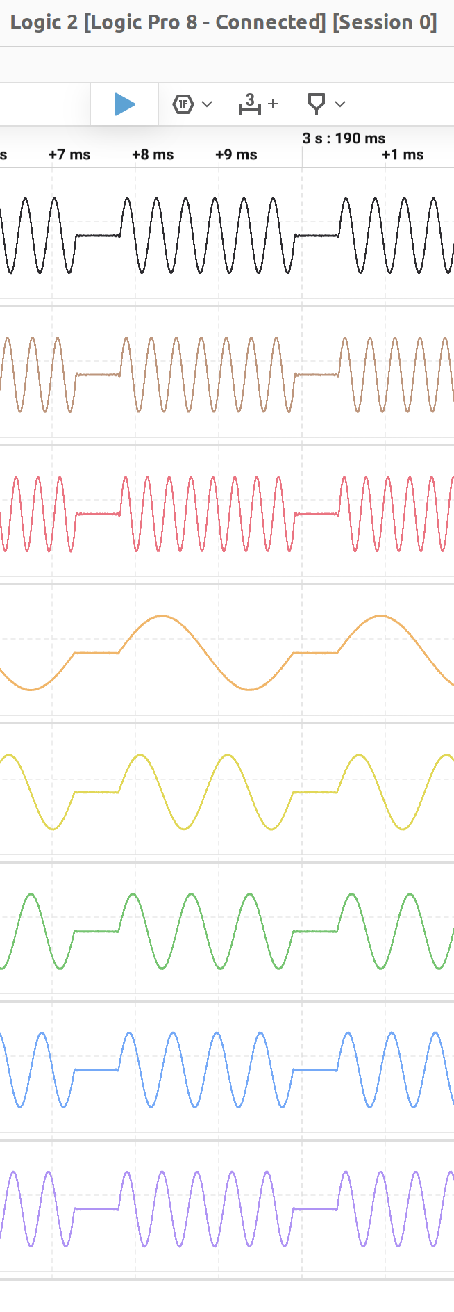
When called without arguments, play() creates test output (right now sine waves of various frequencies separated by gaps) for each DAC channel and sets up the interface to repeatedly send the data to the DACs in the background.
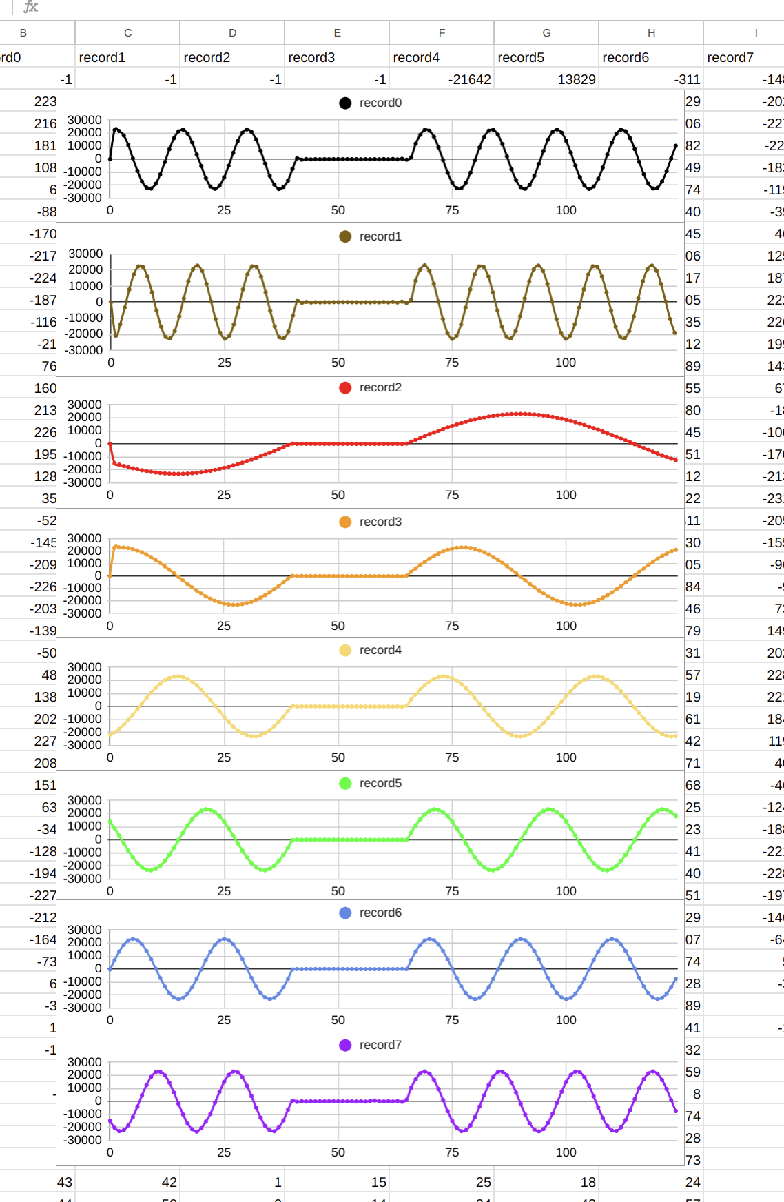
When record() is called without arguments, it creates a buffer the same size as the playing buffer, fills it with ADC samples, and prints out the returned data in
CSV format. The table below compares the DAC outputs as seen on a scope with the ADC outputs plotted on a spreadsheet:
| DAC output | ADC output | |
|---|---|---|
 |  |
Adafruit CircuitPython 9.1.0-beta.0-426-g65556b42a5 on 2025-01-27; Adafruit Feather RP2350 with rp2350a
>>>
>>> import tac5
>>> t = tac5.TAC5(channels=2, width=8, sample_rate=12000, address=None)
>>> t.rec(length=10)
recording...
>>> t.play(length=10, init='count')
playing...
>>> t.show(t.record_loop_buffer)
'sample'; 'ch0'; 'ch1'
0; -10; -9
1; -7; -6
2; -5; -4
3; -4; -3
4; -2; -1
5; 1; 2
6; 2; 3
7; 4; 5
8; 7; 8
9; 9; 10
>>> t.show(t.play_loop_buffer, shift=False)
'sample'; 'ch0'; 'ch1'
0; -10; -9
1; -8; -7Note that the count test data generated by tac5 is offset by 1 in play_loop2_buffer to distinguish it from the other buffer's data.
Adafruit CircuitPython 9.1.0-beta.0-426-g65556b42a5 on 2025-01-27; Adafruit Feather RP2350 with rp2350a
>>>
>>> import tac5
>>> t = tac5.TAC5(channels=2, width=8, sample_rate=12000, address=None)
>>> t.rec(length=10, double_buffer=True)
recording...
>>> t.play(length=10, init='count', double_buffer=True)
playing...
>>> t.show(t.record_loop_buffer)
'sample'; 'ch0'; 'ch1'
0; -10; -9
1; -8; -7
2; -6; -5
3; -4; -3
4; -2; -1
5; 0; 1
6; 2; 3
7; 4; 5
8; 6; 7
9; 8; 9
>>> t.show(t.record_loop2_buffer)
'sample'; 'ch0'; 'ch1'
0; -9; -8
1; -7; -6Adafruit CircuitPython 9.1.0-beta.3-180-geda524f85c-dirty on 2024-10-24; Adafruit Feather RP2040 with rp2040
>>> import tac5
>>> t = tac5.TAC5(channels=2, width=8, sample_rate=12000, address=None)
>>> t.rec(length=10, double_buffer=True)
recording...
>>> t.play(length=10, test='count', double_buffer=True)
playing...
>>> t.show(t.record_loop_buffer)
'sample'; 'ch0'; 'ch1'
0; -9; -8
1; -7; -6
2; -5; -4
3; -3; -2
4; -1; 0
5; 1; 2
6; 3; 4
7; 5; 6
8; 7; 8
9; 9; 10
>>> t.tape('/foo.txt')
Traceback (most recent call last):
File "<stdin>", line 1, in <module>
File "tac5.py", line 347, in tape
KeyboardInterrupt: | Qty | Value | Footprint | References |
|---|---|---|---|
| 4 | R_US | Resistor_SMD:R_0603_1608Metric | R1, R2, R3, R4 |
| 3 | 0.1uF | Capacitor_SMD:C_0603_1608Metric | C4, C6, C7 |
| 3 | 10uF | Capacitor_SMD:C_0603_1608Metric | C1, C3, C5 |
| 2 | Conn_01x12 | Connector_PinHeader_2.54mm:PinHeader_1x12_P2.54mm_Vertical | J1, J2 |
| 1 | 1uF | Capacitor_SMD:C_0603_1608Metric | C2 |
| 1 | TAC5212 | ...timc:VQFN-24-1EP_4x4mm_P0.5mm_EP2.45x2.45mm_ThermalVias | U1 |
google/mozc-devices
Circuit diagrams and firmware source code for Gboard DIY keyboards


hackclub/OnBoard
💡 Join 1,000 teenagers and make your first PCB with a $100 grant!


Twotoz/C5VRX
Ultra-minimal, zero-CPU 5.8 GHz analog FPV video receiver using ESP32-C5 Wi-Fi 6 PHY MODEM_DIAG, BitScrambler WBFM demodulation & resistor DAC CVBS


It measures 17.3 × 30 mm and has 2 copper layers, 1.6 mm thick.
14 parts. The full list of its parts is on this page, with links to each part's symbol and footprint where PCBKit's library has them.
From the timchinowsky/tac5 repository on GitHub, at the commit this page was made from: the board is pcb/tac5/tac5.kicad_pcb and its schematic pcb/tac5/tac5.kicad_sch. PCBKit opens the board in the browser, with nothing to install.
Its repository publishes it under the MIT licence: you may reuse it on that licence's terms (keep the author's notice, and for a copyleft licence share your changes alike).