

2 layers98.3 × 67.9 mm
OV5680 MODULE
tidus747/Adap_multicamara_NJTX2
Desarrollo de la adaptación para multicámara de la Nvidia Jetson TX2. Trabajo de fin de Máster de Iván Rodríguez Méndez dirigido por Fernando Luis Rosa González.
64 parts4GPL-3.0

 tidus747/Adap_multicamara_NJTX24
Desarrollo de la adaptación para multicámara de la Nvidia Jetson TX2. Trabajo de fin de Máster de Iván Rodríguez Méndez dirigido por Fernando Luis Rosa González.
Shield debug is an open-source printed circuit board by tidus747, from the tidus747/Adap_multicamara_NJTX2 repository on GitHub, published under the GPL-3.0 licence. It is a 2-layer board of 100 × 75 mm with 19 parts on 86 nets, routed with 383 tracks and 0 vias.
It is built around the QTH-060-01-H-D-A. It belongs with the computers and single-board computers boards of this library.
Multidisciplinary engineering project covering mechanical design, custom electronics, embedded Linux integration, camera-array calibration and disparity estimation.
Master's Degree Final Project in Industrial Engineering
Author: Iván Rodríguez-Méndez
Supervisor: Fernando Luis Rosa González
Universidad de La Laguna, 2018


The goal of this project was to develop the hardware and software required to operate a multi-camera array around the NVIDIA Jetson TX2.
The work covered the complete engineering chain:
The repository contains the original engineering artifacts, experimental captures and the complete Master's thesis.
flowchart LR
    SCENE[Scene] --> CAM[Camera sensors]
    CAM --> ELEC[Custom camera and bridge electronics]
    ELEC --> JETSON[NVIDIA Jetson TX2]

    MECH[Mechanical camera array] --> CAM
    ADJ[Camera angle adjustment] --> MECH

    JETSON --> KERNEL[Kernel and Device Tree]
    KERNEL --> DRIVER[Camera drivers]
    DRIVER --> GST[GStreamer capture]

    GST --> DATA[Multi-camera datasets]
    DATA --> CAL[Array calibration]
    CAL --> DISP[Disparity estimation]
    DISP --> RESULTS[Experimental results]
See docs/system-architecture.md for the detailed system view.
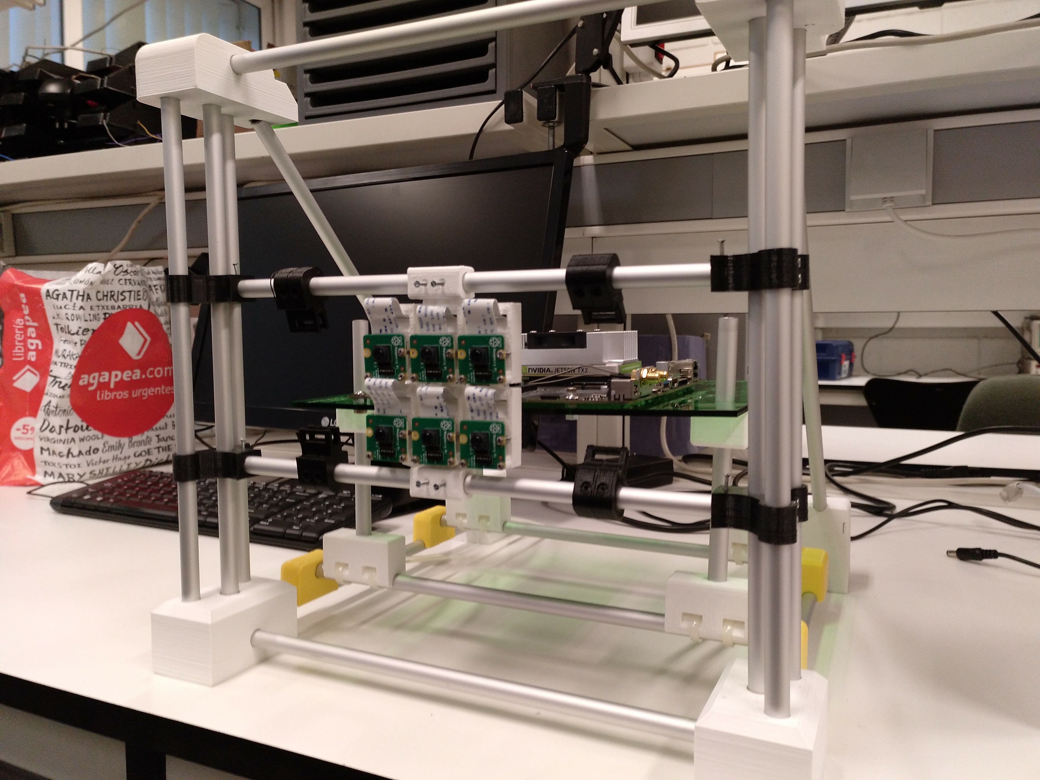
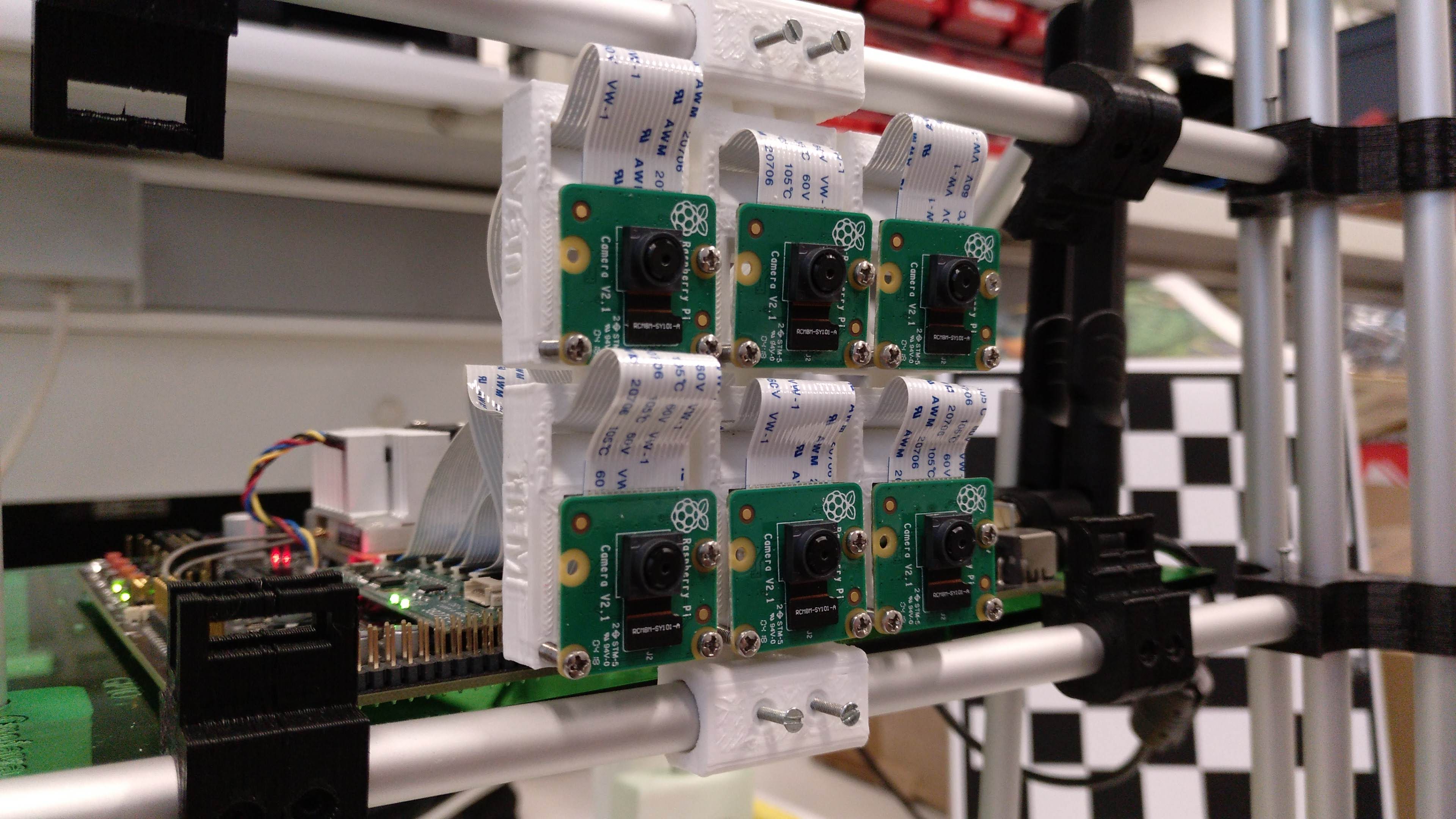
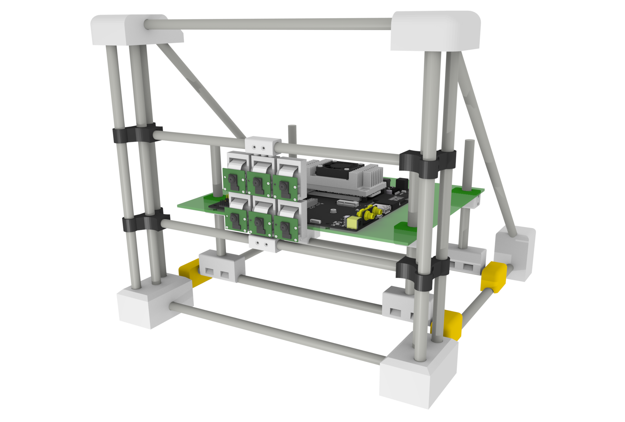
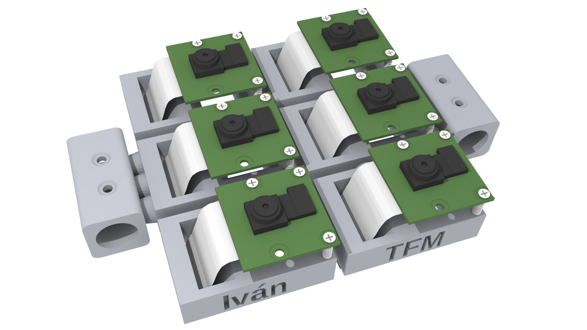
The mechanical subsystem includes:
Source material: Desarrollo_Mecanico
The electronic development includes several prototype and production-oriented modules:
Source material: Desarrollo_Electronico
The Jetson TX2 integration required work below the application layer.
The repository includes:
Source material: Desarrollo_Software
The completed system was used to acquire multi-camera image sets and validate the full integration through calibration and disparity-estimation experiments.
Experimental data: Array_captures
A condensed explanation of the problem, system integration and validation strategy is available in:
docs/engineering-case-study.md
The original Master's thesis is preserved in:
Representative disparity-estimation results obtained with the camera array:
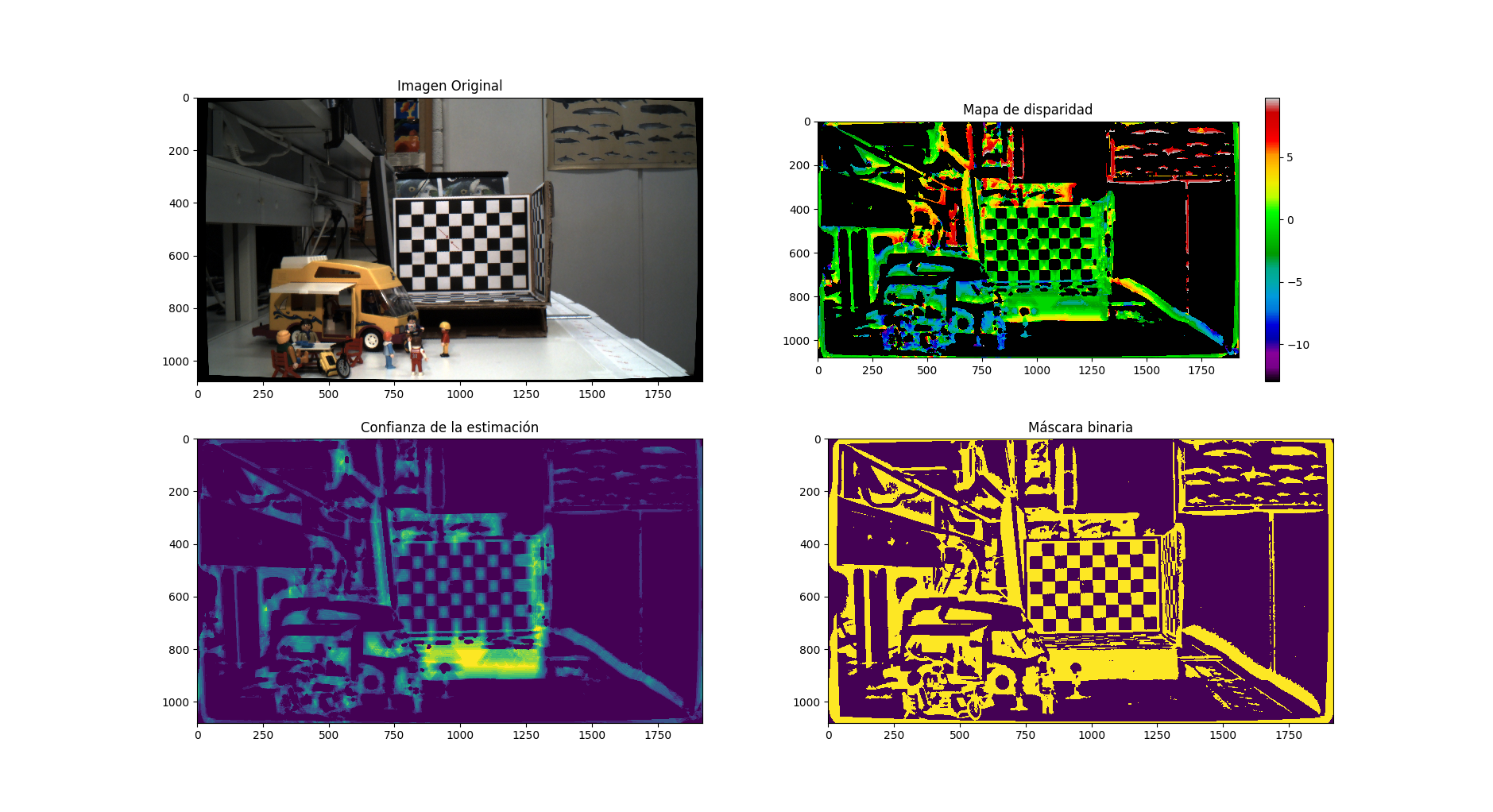
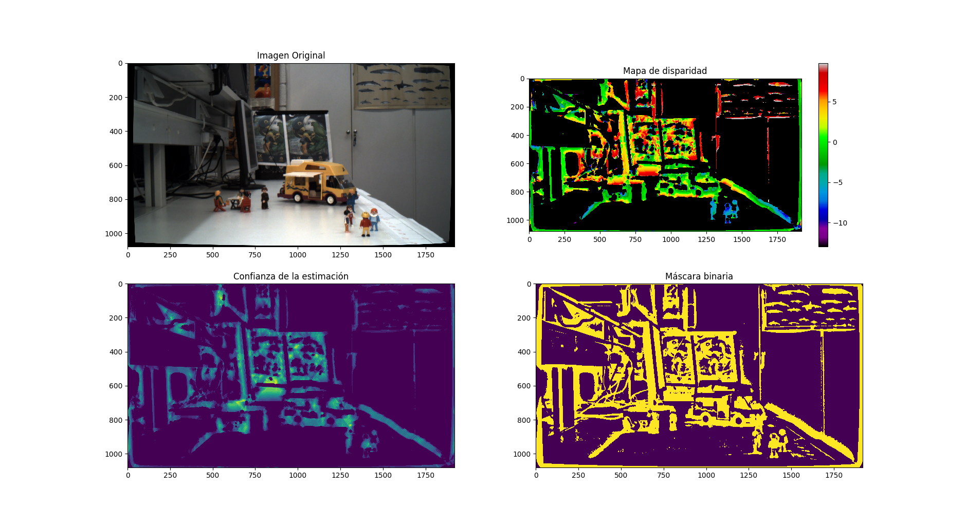
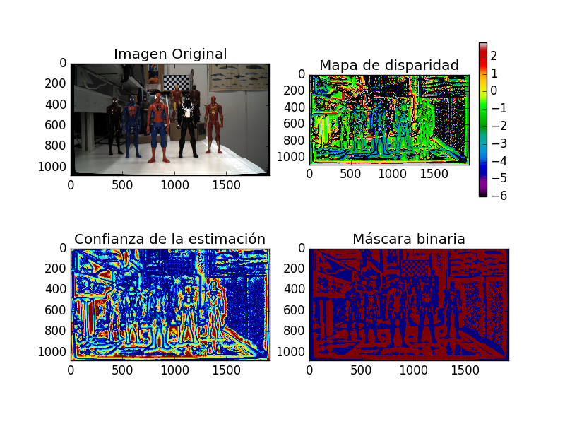
Adap_multicamara_NJTX2/
|-- Array_captures/
|   `-- Experimental multi-camera datasets
|-- Desarrollo_Electronico/
|   `-- Electronic design and fabrication files
|-- Desarrollo_Mecanico/
|   `-- Mechanical design and fabrication files
|-- Desarrollo_Software/
|   `-- Jetson, kernel, drivers, GStreamer and camera scripts
|-- Documentos/
|   `-- Original Master's thesis
|-- docs/
|   |-- engineering-case-study.md
|   `-- system-architecture.md
|-- images/
|   |-- Array_3D /
|   |-- Array_real/
|   |-- Modelo3D_Placas/
|   `-- Resultados/
|-- CONTRIBUTING.md
|-- LICENSE
`-- README.mdThis project is fundamentally an integration project.
The camera system only works when multiple engineering domains work together:
flowchart TD
    SYS[Working multi-camera system]
    ME[Mechanical alignment] --> SYS
    EE[Electronic interfaces] --> SYS
    EMB[Embedded Linux integration] --> SYS
    IMG[Image acquisition] --> SYS
    CAL[Calibration] --> SYS
    CV[Computer vision] --> SYS
It required moving repeatedly between physical design, electronics, low-level software, system bring-up and experimental validation.
This project was developed in 2018 using the NVIDIA Jetson TX2 platform and the JetPack/kernel ecosystem available at that time.
The repository is preserved as an engineering record. Kernel patches, Device Tree files, drivers and software instructions should therefore be treated as historical technical material rather than current Jetson setup instructions.
The original project history is preserved. Future maintenance uses GitFlow without rewriting historical engineering artifacts.
See CONTRIBUTING.md.
Released under the GNU General Public License v3.0. See LICENSE.
| Qty | Value | Footprint | References |
|---|---|---|---|
| 7 | Conn_01x09 | Pin_Headers:Pin_Header_Straight_1x09_Pitch2.54mm | J1, J2, J3, J9, J10, J11, J12 |
| 2 | Conn_01x02 | Pin_Headers:Pin_Header_Straight_1x02_Pitch2.54mm | J5, J6 |
| 2 | Conn_01x07 | Pin_Headers:Pin_Header_Straight_1x07_Pitch2.54mm | J4, J7 |
| 1 | Conn_01x06 | Pin_Headers:Pin_Header_Straight_1x06_Pitch2.54mm | J8 |
| 1 | LOGO | Logotipos :LOGO | G*** |
| 1 | QTH-060-01-H-D-A | QTH-060-01-H-D-A:QTH-060-01-H-D-A | P1 |
The 14 most common of 19 parts.
tidus747/Adap_multicamara_NJTX2
Desarrollo de la adaptación para multicámara de la Nvidia Jetson TX2. Trabajo de fin de Máster de Iván Rodríguez Méndez dirigido por Fernando Luis Rosa González.

tidus747/Adap_multicamara_NJTX2
Desarrollo de la adaptación para multicámara de la Nvidia Jetson TX2. Trabajo de fin de Máster de Iván Rodríguez Méndez dirigido por Fernando Luis Rosa González.

tidus747/Adap_multicamara_NJTX2
Desarrollo de la adaptación para multicámara de la Nvidia Jetson TX2. Trabajo de fin de Máster de Iván Rodríguez Méndez dirigido por Fernando Luis Rosa González.

tidus747/Adap_multicamara_NJTX2
Desarrollo de la adaptación para multicámara de la Nvidia Jetson TX2. Trabajo de fin de Máster de Iván Rodríguez Méndez dirigido por Fernando Luis Rosa González.

tidus747/Adap_multicamara_NJTX2
Desarrollo de la adaptación para multicámara de la Nvidia Jetson TX2. Trabajo de fin de Máster de Iván Rodríguez Méndez dirigido por Fernando Luis Rosa González.

tidus747/Adap_multicamara_NJTX2
Desarrollo de la adaptación para multicámara de la Nvidia Jetson TX2. Trabajo de fin de Máster de Iván Rodríguez Méndez dirigido por Fernando Luis Rosa González.


hackclub/OnBoard
💡 Join 1,000 teenagers and make your first PCB with a $100 grant!

polpo/picogus
Emulation of ISA sound cards and CD-ROM on Raspberry Pi Pico (GUS, SB/Adlib, MPU-401, Tandy, CMS, Panasonic CD-ROM) with USB mouse/joystick support


nkitanov/iaq_board
IAQ Board is a DIY (Do-It-Yourself) device for measuring internal air quality


Ardumower/ardumower
Develop an open source robotic lawn mower (HW+SW reference platform)

zmaker/arduino_cookbook
gli sketch del nuovo progetto Arduino Cookbook e dei video di YouTube
It measures 100 × 75 mm and has 2 copper layers, 1.6 mm thick.
19 parts, built around the QTH-060-01-H-D-A. The full list of its parts is on this page, with links to each part's symbol and footprint where PCBKit's library has them.
From the tidus747/Adap_multicamara_NJTX2 repository on GitHub, at the commit this page was made from: the board is Desarrollo_Electronico/Modulo_Depuracion/Shield_debug.kicad_pcb. PCBKit opens the board in the browser, with nothing to install.
Its repository publishes it under the GPL-3.0 licence: you may reuse it on that licence's terms (keep the author's notice, and for a copyleft licence share your changes alike).