2 layers30.2 × 54.9 mm
Rev2 x ay interposer
thorpej/CoPicoVision
A ColecoVision clone using a Raspberry Pi Pico and pico9918 for video
4 parts13

 thorpej/CoPicoVision13
A ColecoVision clone using a Raspberry Pi Pico and pico9918 for video
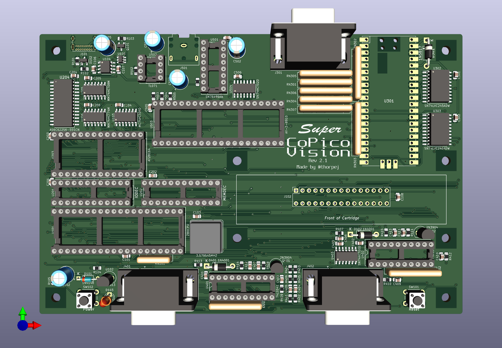
CoPicoVision is an open-source printed circuit board by thorpej, from the thorpej/CoPicoVision repository on GitHub. It is a 4-layer board of 165.9 × 110 mm with 118 parts on 220 nets, routed with 3,292 tracks and 567 vias.
It is built around the SN74LVC245ADW, MC74ACT05D and ICL7660AMTV, with the AS6C62256-55SCN, CD74HCT161M and DS1813-5+ among its other parts. Its parts include 36 capacitors, 28 resistors, 22 ICs, 6 diodes and 6 connectors. It belongs with the RP2040 and FPGA and CPLD boards of this library.


The CoPicoVision stems from yet another bout of nostalgia for a time before photorealistic video games, when all we had was blocky tile graphics and a few bleeps and bloops and gosh darn it, we liked it! When I was a kid, I got a ColecoVision one Christmas and I played the h*ll out of it. Alas, I no longer have it, but I wish I still did, and building a clone seems a lot more fun than over-paying for one on eBay.
Ok, fine, I have a second motive: It also serves as a test mule for using modified variants of Troy Schrapel's excellent pico9918 project, something I'm considering using in other projects, and test mules that can play Mr. Do! and Zaxxon (yes, yes, yes, and Donkey Kong) are the best kinds of test mules.
This work is licensed under the Creative Commons Attribution ShareAlike 4.0 International license.

I've had some time recently to test my one built-up rev 2.0 board (with all of the necessary rework performed). I found that one rework procedure was incomplete, and therefore I'm recommending that others do not build up any 2.x boards at this time. I managed to spot the problem and avoided damaging any chips, but I'd rather be safe than sorry. I also discovered another bug, of sorts, in the memory decoding logic when testing an SGM game ("1942"). Spoiler alert: SGM games are not working correctly yet. The issue revolves around the way address lines A10-A12 are gated to provide the stock ColecoVision RAM "mirroring" behavior. Those lines are gated too aggressively, and a change to the MEMDEC GAL and a change to the input signal to the 74HCT08 that gates those lines was required. I discovered this using a memory map test utility I wrote for this purpose. I still don't understand how this bug would break "1942", though, so I still have some work to do.
I received the rev 2.0 boards a little while ago, and the other night started building one up, only to realize I forgot to oder some parts. Oh well, no big deal... I have some travel planned for the next few days, and when I get back, the parts will be here. I'm continuing to make tweaks to the rev 3.0 board, replacing through-hole components with surface-mount equivalents; it's really amazing how much faster it is to build up a board with surface-mount bits. The rev 2.0 CoPicoVision is by far my most ambitious SMT project to date, and rev 3.0 will be even MOAR.
I've settled on rev 3.0 being the final "classic" CoPicoVision (barring bugs, obviously), but I am already thinking about a rev 4.0 that will eliminate the out-of-production audio chips in favor of a second Pi Pico that will emulate both the SN76489AN and the AY-3-8910. I'm going to spend a lot of time breadboarding that before I make the leap, but it's my goal to eliminate those hard to source parts. Only the Z80A will remain, and it's still somewhat available (for now, at least).
I've done some work to update to the latest version of pico9918, and submitted a PR for my build parameterization changes.
Ok, I am tagging rev 2.1 that contains the MEMDEC fix and has a rework procedure involving an interposer board for the AY-3-8910 clock issue. I don't plan to actually spin any of these boards myself, but it's a checkpoint (and I am spinning a run of interposers).
Happy New Year, everyone!
Aaaaand I've realized I made another error, this time in the SGM extended memory support. Specifically, when disabling the BIOS ROM. I foolishly used /WR as an input signal to the decoder, completely forgetting the fact that the Z80 memory cycle timings are very different from the I/O cycle timings. To fix this, I'm going to need to change the MEMDEC GAL inputs and equations (it should take /RD as an input rather than /WR). I will post a re-work for the rev 2.0 boards (it will involve cutting a trace and running a short bodge wire between the Z80 and the MEMDEC GAL).
I've realized that I made a major error in the clock frequency for the AY-3-8910, and this is going to require me to spin the board. Basically, I used the CPUCLK as the input to the AY-3-8910, when it actually needs to be divided by 2. I can do that by adding a D-FF. I'll make an interposer board for rev 2.0 systems that sits between the AY-3-8910 and the main board that carries the FF chip. If that works out OK, I'll just probably put that down on the main board in rev 3.0, rather than overhauling the whole clock circuit.
Ok, I think I'm going to tag a 2.0 pre-release and get the boards off to fabrication. I don't really anticipate making any more board changes in the short term -- just hanges to ancillary documents. So stay tuned for that!
Well, I had some time to kill on a plane, so I started the process to claw back board real estate in order to fit the additional components needed for "Super CoPicoVision". But of course, once the initial shrink was done, I needed to know where the additional components would fit before I re-routed the board. This of course meant that I needed to actually add these additional components to the board, meaning that I needed to do the work to add them to the schematic. Anyway, you can probably guess where this is going! I need to now fix up the BOM (when you're ordering ICs in surface-mount packages, you need to be a little more specific about which part number you order!)
I had to take a break from CoPicoVision for a little while for various reasons, but I'm trying to get back to it. After mulling it over and thinking about future "Super CoPicoVision" plans, I decided to change the audio output buffer to a TL071 opamp, taking advantage of the -5V rail I have at my disposal. I added an LTspice simulation of the circuit, including passively mixing in the output of an AY-3-8910, which would be present on this hypothetical "Super CoPicoVision". I want to get this send off to the fab soon and if everthing is fine, call this version "CoPicoVision 1.0".
I do plan to keep working on it, though! I plan on experimenting with the layout, switching to SMT components as necessary, to see if I can fit the extra chips needed for the Super flavor within the same board footprint.
I finally got a chance to get set up with some powered speakers (with a volume control) to get a better sense of how the audio section behaves. With the AudioEngine 2+ speakers I tested with, the noise isn't really that bad at all, and it definitely seems to be a property of the SN76489AN (placing my finger on top of the chip while running makes an audible different in the noise profile).
I haven't yet bodged the audio section changes in revision 0.2 onto this revision 0.1 board. I really should try to do that soon and re-evaluate.
I've updated the schematic and PCB to fix the swapped controller bug in the rev 0.1 boards, and bumped the revision to 0.2.
I've also built up the audio section of the board and confirmed that it works. It's not ideal, though:
Built up the controller section and played some Donkey Kong! I did make a mistake on the controller section, however. Controller 1 and 2 are swapped. I will correct this in the next revision of the board, and there is a procedure to fix the rev 0.1 boards that I've already run off.
There also a mistake in the physical placement of the card edge connector for the cartridge. It's a few millimeters too close to the front of the board, and so the cartridge bumps into one of the 2N3904s in the controller circuit and the cartridge doesn't quite align with the silk screen outline. That's going to be a little tricker to fix because I might have to re-route some of the board, but I'll fix that up as well.
Guess I should build the audio section next!
After replacing a bad oscillator, the first test board is working! I have not yet installed the audio or controller circuitry yet, but I can boot up Donkey Kong and Buck Rogers, and, due to the lack of controller circuitry being misinterpreted as input, game play starts!
Boards have been back for a while now, and I finally got around to starting to build one up. Thought I had all of the resistors I needed in my inventory, but alas, I did not, so need to place a Jameco order!
I made some small adjustments to the PCB, and sent rev 0.1 off for fabrication!
I made forks of pico9918 and vrEmuTms9918 in order to make the changes needed for CoPicoVision, and then went ahead and made all of those changes. Initial firmware version checked in!
The initial "rev 0.1" hardware design is done and ready to send off for fabrication. There is some software work to do on the pico9918 side of things, but the changes I have in mind are trivial. My plan is to wrap my changes in proper configuration options and feed those changes back to Troy.
So, yah, it's early! Watch this space!
My initial goal was to play ColecoVision games (and subsequently, also games that require the Super Game Module), not to produce a faithful clone of the circuit. It needs to be fully-compatible with ColecoVision and SGM games, but that's the extent of it. As such, some shortcuts are going to be taken.
First of all, I'm using Troy Schrapel's excellent pico9918 engine for the video display. This reduces the number of vintage parts that need to be sourced, and gives me VGA video output. I won't be using the pico9918 as-is, however; since I don't need all of the outputs of a real TMS9918A (no CPUCLK or GROMCLK), I'm using a modified pico9918 firmware that doesn't bother with those outputs and thus allows me to use a regular Raspberry Pi Pico as a module.
Second of all, I'm not going to bother with the expansion interface; I don't particularly care about connecting an Adam module, and if I ever do, then it will be time to re-evaluate my life choices.
And lastly, as should be obvious through my use of a microcontroller that's hundreds of times more powerful than the ColecoVision itself, I have no qualms about using programmable logic to reduce the part count and generally simplify the design. In particular, this means GAL22V10s for address decoding and other glue logic rather than general-purpuse 7400-series parts. Atmel still makes a compatible part, and there are open source tools for programming them, so the design is still very accessible.
There are three "vintage" parts that are required for the CoPicoVision:
Eventually, I'd like to replace the SN76489AN and AY-3-8910s with emulated parts, (almost certainly using a Pi Pico), but for now the real thing needs to be sourced.
Obviously, with the Z80 now being EOL'd, that poses a bit of a snag. Luckily, I have a stash of modern CMOS Z80s, and this design will also accept a vintage NMOS Z80. The CPU is clocked at 3.57MHz, so a Z80A or better is necessary. Maybe one day I'll evaluate one of the FPGA Z80 cores floating around to see if it's feasible to use one of those with an iCE40 FPGA in an updated version of the CoPicoVision. But for now, a genuine Z80 must be used.
I spent some time mulling over how I wanted to approach this board. I considered doing an all-SMT board (except for the stuff that was only available as through-hole), but for the first version of the board I ultimately went with mostly through-hole parts (except for the power supply) in order to try and keep a more retro look.
This wasn't feasible for version 2, the "Super CoPicoVision"; I wanted to keep the same basic envelope, so I had no choice to shrink the components in order to make space for the additional logic chips and the large DIP-40 AY-3-8910. So, I converted all of the individual resistors and ceramic capacitors to 0805 packages, and the RAM and most logic ICs to SOIC packages (I left the 74LS541s in the controller input section as DIP packages).
The board is 4 layers: signals (and ground fill) top and bottom, along with an internal ground plane and power plane. I arrived at the size of the board through experimentation; essentially, I did a rough layout of the board into what I thought "looked pretty good", placed mounting holes and keep-outs, and then drew an edge-cut box around it. Once the box was drawn, I tried to stay within that envelope. I'm a total novice when I comes to PCB layout and design, and I routed the entire board by hand, but did manage to make it fit. Some signals are routed, ahem, interestingly, but this isn't a high-speed design so it should be just fine.
The font of the board has power and reset buttons and the 2 controller ports. The rear of the board has power, audio, and VGA jacks, along with the USB connector for the Raspberry Pi Pico in case there's a need to update the pico9918 firmware. There's a diode in between the Pico and the rest of the board, so it's safe to update the firmware in situ.
I've included a bill of materials with Mouser part numbers for just about everything, including the jellybean SMT resistors / capacitors in standard 0805 packages; these jellybean parts can be substituted with equivalent stock you might have on hand, of course, but I included Mouser part numbers for convenience. For the DIP chip sockets, you whatever kind you prefer. For the push button switches, there are lots of garden-variety 6mm through-hole momentary push buttons out there, so you whatever you prefer.
The power supply is fairly simple, since we don't need the -12V rail that's found on the original ColecoVision. We do, however, require a -5V rail, which is used as a bias voltage in the controller interface circuit as well as for the op-amp used as an output buffer in the audio circuit.
Power comes in via a USB-C connector (with ESD protection diodes on the control channel signals). Power is switched using a MAX16054 on/off supervisor chip that controls a high-side P-FET to supply power to the rest of the system. The MAX16054 is controlled using a single momentary pushbutton.
The -5V rail is generated using an ICL7660A charge pump chip.
On the first revision of the CoPicoVision, the clock circuit was as simple as it gets: a simply a 3.579545 MHz DIP-8 oscillator can that drove the whole thing, providing CPUCLK signal to the Z80, the M1 wait-state generator, and the SN76489AN sound chip.
When the Super Game Module enhancements were added in rev 2.0, this clock was also provided to the AY-3-8190 sound chip, which was actually a mistake on my part, and it required an annoying work-around to divide CPUCLK by 2 for the AY-3-8190.
So, in rev 3.0, the clock circuit was completely overhauled to use a 14.31818 MHz oscillator to generate the base clock, which is fed into a 74HCT161 binary counter that is used to divide the base frequency by 4 (CPUCLK - 3.579545 MHz) and 8 (AYCLK - 1.789773 MHz).
The reset circuit is based on the DS1813 reset generator IC, which also de-bounces the reset button. There is a small RC network that makes the power-on-reset slightly longer than a manual reset.
Address decoding is performed using 2 GAL22V10 programmable logic devices. The original ColecoVision uses 2 74LS138s for address decoding, but also requires some extra logic to invert some of the signals used by the decoders. By using GALs for this purpose, I save the extra logic chips.
The ColecoVision also uses a 74LS74 dual D-type flip-flop along with some additional logic gates to add a wait-state when the Z80 performs an opcode fetch. It does this presumably to give some extra breathing room to slow ROMs (of the Z80 machine cycles, M1 has the tightest timing). There is plenty of space in the MEMDEC GAL for this, so that's where I put it. There is a large comment in the MEMDEC GAL source file that explains how the wait-state generator works.
The BIOS ROM for the CoPicoVision is contained in a 150ns 28C64 EEPROM. I chose this part because:
The CoPicoVision's RAM is an AS6C62256-55SCN, which is a 32KB 55ns SRAM chip.
The ColecoVision's memory address space is divided into 8 8KB "pages":
The ColecoVision only has 1KB of RAM at $6000, and the addresses are incompletely decoded, so that 1KB is mirrored throughout that page.
The Super Game Module has 32KB of extended RAM, only 24KB of which is available unless the BIOS ROM is diabled. These features are controlled by the following two registers:
The CoPicoVision uses a 74HCT74 dual D-type flip-flop to provide these two control registers (only 2 independently-settable bits are needed). FF1 is connected to D0 and provides the XRAMEN signal, and FF2 is connected to D1 and provides the ROMEN signal. The /RESET line is connected such that FF0 is cleared at reset and FF1 is set at reset. These two signals are used by the MEMDEC GAL when decoding memory addresses. A 74HCT08 quad-AND chip mixes the XRAM signal with RAM address lines A10-A12, forcing them to 0 when XRAMEN is disabled and passing them through from the CPU when XRAMEN is enabled, thus maintaining the RAM mirroring behavior of the original ColecoVision.
When the ROM is enabled, MEMDEC sends reads from the $0000 page to the ROM, and when disabled it sends those reads to the RAM. Writes to the $0000 page are always sent to RAM. On the CoPicoVision, the $0000 page RAM behavior is governed entirely by the ROMEN signal. I suspect this doesn't exactly match the original Super Game Module behavior, but I also suspect that it doesn't matter in any practical sense.
I/O address decoding is handled by the IODEC GAL. In the original ColecoVision, I/O addresses were incompletely decoded using address lines A5-A7:
To support the SGM extensions, the IODEC GAL also needs to completely decode the following addresses:
A pair of NOR gates from a 74HCT02 are used in conjunction with the /AYSEL output from IODEC, the A0 address line, and the Z80's /WR signal to generate the BC1 and BDIR signals used to interface with the AY-3-8910.
The audio section is comprised of the two sound chips, whose outputs are passively mixed using 1K series resistors and then AC-coupled to a TL071 op-amp which serves as an output buffer. The op-amp's output is then AC-coupled to both outputs of a 3.5mm TRS phone jack.
Of course, the video circuit is built using a Raspberry Pi Pico running a modified version of the pico9918 firmware. The following changes from the base pico9918 have been made:
The bus interface to the Pico is a little simpler than that used on the pico9918. Two 74LVC245 bus transceivers are used to perform the 3V3 <--> 5V level shift. This works perfectly fine since I've arranged for everything on the 5V side to use TTL logic levels, which can accept the 3V3 CMOS logic level outputs. One transceiver is hard-wired for the B->A direction and level-shifts the A0, /VDPWSEL, /VDPRSEL, and /RESET input signals to the Pico. The other transceiver level-shifts the data bus and takes care of swizzling the bit order between the VDP and the Z80. The IODEC GAL generates an extra signal that's used to enable the output of the data bus transceiver, and the direction of the transceiver is controlled by /VDPWSEL.
The VGA resistor DAC is identical to the pico9918's.
The controller interface is derived more or less straight from the ColecoVision, except the quad-NAND gate is replaced with a 74HCT part. The controller input buffers are the same 74LS541 used on the original because the circuit relies on Schmitt trigger inputs and the standard CMOS replacement parts don't have them. Eventually I may experiment with the 74HCS541 as a replacement.
One difference is that I made both controller inputs indentical; in the original, it seems that one controller input was drawn in a "mirror image" and the bit order on it's buffer swapped to compensate. That seemed needlessly confusing to me, so I just made them both the same (I literally copy-and-pasted, and then tweaked some net labels to make the second instance).
The controller interface is by far the most complicated block on the system. I have a basic understanding of how it works, but there is clearly some subtle analog magic going on, so I decided not to push my luck. I don't have any of the quadrature controllers to test with at this time.
Rev 2.x of the CoPicoVision has the following bugs:
Rev 2.0 of the CoPicoVision has the following bugs:
Rev 0.1 of the CoPicoVision has the following bugs:
This contains corrections / additions to the Bill of Materials. There are no circuit or board changes in this revision.
This is the first revision of the Super CoPicoVision!
First of all, I want to say that I was inspired to take a crack at this by the Leako project, which you can read about here.
Second, huge shout out to ChildOfCv on the AtariAge forums for their fantastic reverse-engineered ColecoVision schematics.
And finally, massive thanks to Troy for his fantastic pico9918. It's truly what makes the CoPicoVision possible.
If you have any questions about the board, you can reach out to me on Twitter (@thorpej) or Mastodon (@thorpej@mastodon.sdf.org). You can also check out my YouTube channel, which has this and other retrocomputing related content.
| Qty | Value | Footprint | References |
|---|---|---|---|
| 21 | 0.1µF | Capacitor_SMD:C_0805_2012Metric_Pad1.18x1.45mm_HandSolder | C101, C103, C104, C108, C109, C201, C202, C203, C204, C205, C206, C301, C302, C401, C402, C403 +5 |
| 8 | MountingHole | MountingHole:MountingHole_3.5mm | H101, H102, H103, H104, H105, H106, H107, H108 |
| 7 | 1K | Resistor_SMD:R_0805_2012Metric_Pad1.20x1.40mm_HandSolder | R301, R302, R303, R501, R503, R504, R505 |
| 4 | 0.01µF | Capacitor_SMD:C_0805_2012Metric_Pad1.18x1.45mm_HandSolder | C404, C405, C412, C413 |
| 4 | 10K | Resistor_SMD:R_0805_2012Metric_Pad1.20x1.40mm_HandSolder | R103, R409, R412, R502 |
| 3 | 1.5K | Resistor_SMD:R_0805_2012Metric_Pad1.20x1.40mm_HandSolder | R403, R404, R413 |
| 3 | 1K | Package_SO:SOIC-16_3.9x9.9mm_P1.27mm | RN301, RN302, RN303 |
| 2 | .047µF | Capacitor_SMD:C_0805_2012Metric_Pad1.18x1.45mm_HandSolder | C408, C410 |
| 2 | 1.8K | Resistor_SMD:R_0805_2012Metric_Pad1.20x1.40mm_HandSolder | R407, R410 |
| 2 | 100K | Resistor_SMD:R_0805_2012Metric_Pad1.20x1.40mm_HandSolder | R414, R415 |
| 2 | 100pF | Capacitor_SMD:C_0805_2012Metric_Pad1.18x1.45mm_HandSolder | C407, C411 |
| 2 | 100µF | Capacitor_THT:CP_Radial_D6.3mm_P2.50mm | C102, C105 |
| 2 | 10µF | Capacitor_SMD:C_0805_2012Metric_Pad1.18x1.45mm_HandSolder | C106, C107 |
| 2 | 120R | Resistor_SMD:R_0805_2012Metric_Pad1.20x1.40mm_HandSolder | R405, R406 |
| 2 | 1N4001 | Diode_THT:D_DO-41_SOD81_P10.16mm_Horizontal | D401, D402 |
| 2 | 2.2µF | Capacitor_THT:CP_Radial_D6.3mm_P2.50mm | C503, C504 |
| 2 | 220R | Resistor_SMD:R_0805_2012Metric_Pad1.20x1.40mm_HandSolder | R401, R402 |
| 2 | 22K | Resistor_THT:R_Array_SIP8 | RN401, RN402 |
| 2 | 22K | Resistor_SMD:R_0805_2012Metric_Pad1.20x1.40mm_HandSolder | R408, R411 |
| 2 | 5K1 | Resistor_SMD:R_0805_2012Metric_Pad1.20x1.40mm_HandSolder | R101, R102 |
| 2 | 74LS541 | Package_DIP:DIP-20_W7.62mm_Socket | U401, U402 |
| 2 | GAL22V10 | Package_DIP:DIP-24_W7.62mm_Socket | U201, U202 |
| 2 | MMBT3904T | Package_TO_SOT_SMD:SOT-523 | Q401, Q402 |
| 2 | SN74LVC245ADW | Package_SO:SOIC-20W_7.5x12.8mm_P1.27mm | U302, U303 |
| 2 | SW_Push | Button_Switch_THT:SW_PUSH_6mm | SW101, SW102 |
| 1 | 14.31818MHZ | Oscillator:Oscillator_DIP-8 | X101 |
| 1 | 1N4148 | Diode_THT:D_DO-35_SOD27_P7.62mm_Horizontal | D101 |
| 1 | 1N5817 | Diode_THT:D_DO-41_SOD81_P10.16mm_Horizontal | D301 |
| 1 | 22µF | Capacitor_THT:CP_Radial_D6.3mm_P2.50mm | C502 |
| 1 | 330R | Resistor_SMD:R_0805_2012Metric_Pad1.20x1.40mm_HandSolder | R105 |
| 1 | 3K3 | Resistor_SMD:R_0805_2012Metric_Pad1.20x1.40mm_HandSolder | R104 |
| 1 | 3K3 | Resistor_THT:R_Array_SIP5 | RN101 |
| 1 | AS6C62256-55SCN | Package_SO:SOIC-28W_7.5x18.7mm_P1.27mm | U204 |
| 1 | AT28C64 | Package_DIP:DIP-28_W15.24mm_Socket | U203 |
| 1 | AY-3-8910 | Package_DIP:DIP-40_W15.24mm_Socket | U503 |
| 1 | AudioJack3 | Connector_Audio:Jack_3.5mm_CUI_SJ1-3523N_Horizontal | J501 |
| 1 | CD74HCT161M | Package_SO:SOIC-16_3.9x9.9mm_P1.27mm | U106 |
| 1 | Conn_02x15_Odd_Even | jrt-Connectors:Sullins_Cart_Slot | J102 |
| 1 | Controller 1 | Connector_Dsub:DSUB-9_Male_Horizontal_P2.77x2.84mm_EdgePinOffset7.70mm_Housed_MountingHolesOffset9.12mm | J401 |
| 1 | Controller 2 | Connector_Dsub:DSUB-9_Male_Horizontal_P2.77x2.84mm_EdgePinOffset7.70mm_Housed_MountingHolesOffset9.12mm | J402 |
| 1 | DE15_Receptacle_HighDensity_MountingHoles | Connector_Dsub:DSUB-15-HD_Female_Horizontal_P2.29x1.98mm_EdgePinOffset8.35mm_Housed_MountingHolesOffset10.89mm | J301 |
| 1 | DS1813 | Package_TO_SOT_SMD:SOT-23 | U102 |
| 1 | ESDA25L | Package_TO_SOT_SMD:SOT-23 | D102 |
| 1 | ICL7660A | Package_SO:SOIC-8_3.9x4.9mm_P1.27mm | U104 |
| 1 | MAX16054 | Package_TO_SOT_SMD:SOT-23-6 | U105 |
| 1 | MC74ACT05D | Package_SO:SOIC-14_3.9x8.7mm_P1.27mm | U103 |
| 1 | MM74HCT08M | Package_SO:SOIC-14_3.9x8.7mm_P1.27mm | U205 |
| 1 | MM74HCT74M | Package_SO:SOIC-14_3.9x8.7mm_P1.27mm | U206 |
| 1 | MMFTP3334K-AQ | Package_TO_SOT_SMD:SOT-23 | Q101 |
| 1 | Pico | jrt-RPI_Pico:RPi_Pico_SMD_TH | U301 |
| 1 | Power LED | LED_THT:LED_D3.0mm | D103 |
| 1 | SN74HCT00D | Package_SO:SOIC-14_3.9x8.7mm_P1.27mm | U403 |
| 1 | SN74HCT02D | Package_SO:SOIC-14_3.9x8.7mm_P1.27mm | U504 |
| 1 | SN76489AN | Package_DIP:DIP-16_W7.62mm_Socket | U501 |
| 1 | TL071 | Package_DIP:DIP-8_W7.62mm_Socket | U502 |
| 1 | USB_C_Receptacle_PowerOnly_6P | Connector_USB:USB_C_Receptacle_GCT_USB4085 | J101 |
| 1 | Z80CPU | Package_DIP:DIP-40_W15.24mm_Socket | U101 |
thorpej/CoPicoVision
A ColecoVision clone using a Raspberry Pi Pico and pico9918 for video

Sierra-Lobo/mainboard-hardware
PyCubed mainboard v5 fork by Sierra Lobo for Foras Promineo CubeSat


punkfab/pcb-corpus
235 real KiCad boards from open-source hardware repositories, prepared as a placement and routing benchmark


HaddiS2/Complete-Field-Oriented-Control-Module-for-BLDC-Motors-BO26EB-41
Custom field-oriented control (FOC) motor controller with USB-C Power Delivery.
It measures 165.9 × 110 mm and has 4 copper layers, 1.6 mm thick.
118 parts, built around the SN74LVC245ADW, MC74ACT05D, ICL7660AMTV and AS6C62256-55SCN. The full list of its parts is on this page, with links to each part's symbol and footprint where PCBKit's library has them.
From the thorpej/CoPicoVision repository on GitHub, at the commit this page was made from: the board is design-files/CoPicoVision.kicad_pcb and its schematic design-files/CoPicoVision.kicad_sch. PCBKit opens the board in the browser, with nothing to install.
Its repository states no licence, so its author keeps all rights: ask thorpej before reusing the design.