
4 layers100 × 70 mm

A custom-designed robotics Power Supply Unit (PSU) featuring multi-rail buck regulation, remotely switchable outputs, current monitoring, and a hardware E-Stop loop.
PSU is an open-source printed circuit board by Thoric16, from the Thoric16/Power-Supply-Unit repository on GitHub. It is a 4-layer board of 230 × 60 mm with 157 parts on 120 nets, routed with 689 tracks and 51 vias.
It is built around the RGA4W250W020A-001, ADS7828E and MMBT2222A, with the IRLZ44N, XT60PW-F and 01000066Z among its other parts. Its parts include 58 resistors, 24 transistors, 21 connectors, 19 capacitors and 13 diodes. It belongs with the power and robots and motor control boards and the RP2040 boards of this library.


A custom-designed, high-reliability Power Supply Unit (PSU) engineered to act as the centralized power management hub and hardware safety backbone for an advanced robotics platform. This board safely bridges high-draw actuator systems with sensitive compute electronics, featuring real-time telemetry and integrated fault protection.
| Managed Output Domain | Power Characteristic | Safety / Control Mechanism |
|---|---|---|
| Compute Payloads | Stable, Low-Noise Regulated | Upstream Overcurrent Monitored |
| Sensor Electronics | High-Precision Filtered | Soft-Switch Controlled |
| Chassis Drivetrain | High-Draw / Unregulated | Instantaneous Hardware E-Stop Cutoff |
| Robotic Arm Drives | High-Draw / Unregulated | Instantaneous Hardware E-Stop Cutoff |
The PCB layout utilizes broad power planes and deliberate copper pours to handle high-current distribution safely while maintaining a tight, compact form factor. Signal lines for telemetry monitoring are physically isolated away from high-switching buck regulators to mitigate electromagnetic interference (EMI).
Below is the physical validation of the manufactured and populated PSU PCB assembly:
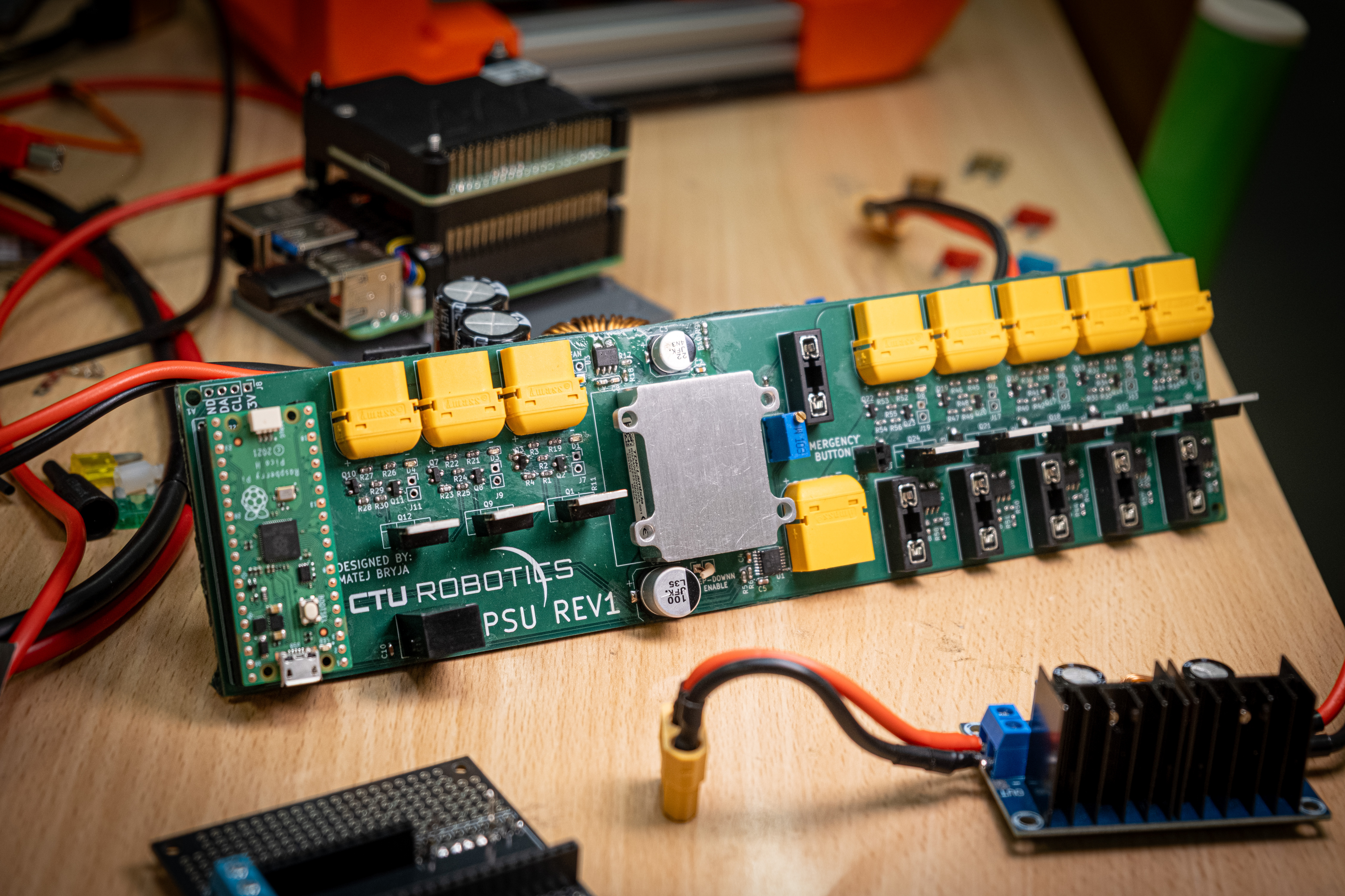
/hardware: Contains the complete source schematic (.kicad_sch) and multi-layer board layout files (.kicad_pcb)./assets: High-resolution photographs.| Qty | Value | Footprint | References |
|---|---|---|---|
| 30 | 10k | Resistor_SMD:R_0603_1608Metric | R1, R4, R10, R11, R14, R16, R17, R18, R23, R25, R28, R30, R33, R35, R36, R37 +14 |
| 16 | 1k | Resistor_SMD:R_0603_1608Metric | R2, R3, R13, R15, R22, R24, R27, R29, R32, R34, R39, R41, R46, R48, R53, R55 |
| 16 | MMBT2222A | Package_TO_SOT_SMD:SOT-23 | Q2, Q3, Q4, Q5, Q7, Q8, Q10, Q11, Q13, Q14, Q16, Q17, Q19, Q20, Q22, Q23 |
| 10 | Conn_01x02_Pin | Connector_PinSocket_2.54mm:PinSocket_1x02_P2.54mm_Vertical | J2, J6, J7, J9, J11, J13, J15, J17, J19, J21 |
| 8 | ? | Resistor_SMD:R_0603_1608Metric | R19, R20, R21, R26, R31, R38, R45, R52 |
| 8 | IRLZ44 | Custom:TO-220-3_Vertical_custom | Q1, Q6, Q9, Q12, Q15, Q18, Q21, Q24 |
| 8 | LED | LED_SMD:LED_0603_1608Metric | D1, D2, D3, D4, D5, D6, D7, D8 |
| 8 | XT60PW-F | Connector_AMASS:AMASS_XT60PW-F_1x02_P7.20mm_Horizontal | J1, J3, J10, J12, J14, J16, J18, J20 |
| 7 | 0.1u | Capacitor_SMD:C_0603_1608Metric | C2, C6, C8, C12, C14, C16, C18 |
| 6 | 01000066Z | Custom:01000066Z | F1, F2, F3, F4, F5, F6 |
| 6 | 1n | Capacitor_SMD:C_0603_1608Metric | C7, C9, C13, C15, C17, C19 |
| 6 | ACS712xLCTR-30A | Package_SO:SOIC-8_3.9x4.9mm_P1.27mm | U2, U3, U4, U5, U6, U7 |
| 5 | US1M | Diode_SMD:D_SMA | D10, D11, D12, D13, D14 |
| 2 | 2k | Resistor_SMD:R_0603_1608Metric | R5, R6 |
| 2 | 4.7u | Capacitor_SMD:C_0603_1608Metric | C10, C11 |
| 1 | 100n | Capacitor_SMD:C_0603_1608Metric | C4 |
| 1 | 100u | Capacitor_SMD:CP_Elec_10x10.5 | C1 |
| 1 | 10u | Capacitor_SMD:C_0603_1608Metric | C5 |
| 1 | 220k | Resistor_SMD:R_0603_1608Metric | R12 |
| 1 | 22u | Capacitor_SMD:CP_Elec_8x6.2 | C3 |
| 1 | 47k | Resistor_SMD:R_0603_1608Metric | R9 |
| 1 | ADS7828 | Package_SO:TSSOP-16_4.4x5mm_P0.65mm | U1 |
| 1 | Conn_01x04_Pin | Connector_PinHeader_2.54mm:PinHeader_1x04_P2.54mm_Vertical | J8 |
| 1 | FAN | Connector_PinSocket_2.54mm:PinSocket_1x02_P2.54mm_Vertical | J5 |
| 1 | LOGO | LOGO | G*** |
| 1 | RBT20W24S05 | Custom:RBT20W24S05 | PS2 |
| 1 | RGA4W250W020A-001 | Custom:RGA4W250W020A001 | PS1 |
| 1 | R_Potentiometer_Trim | Potentiometer_THT:Potentiometer_Bourns_3296W_Vertical | RV1 |
| 1 | RaspberryPi_Pico | Module:RaspberryPi_Pico_Common_THT | A1 |
| 1 | XT60PW-M | Connector_AMASS:AMASS_XT60PW-M_1x02_P7.20mm_Horizontal | J4 |
The 153 most common of 157 parts.


ErdemA33/stm32f405-flight-controller
Open-source ArduPilot-compatible flight controller for fixed-wing UAVs. STM32F405, 4-layer KiCad design, built in 5 modular stages.

AdvikChitre/MSL_Imperial_2023
Repository for Imperial College London Robocup MSL team 2023

foukouda/OPEN_PHASE
OPEN_PHASE: 3-phase inline current and voltage sensing PCB for BLDC drone motors (OPEN THRUST LAB). 1 mΩ shunts + INA241A2 (enhanced PWM rejection), AD7606C-18 18-bit 1 MSPS simultaneous-sampling ADC, LT8362 + LT3045-1…

UCSD-Silberman-Classes-and-Projects/148-winter-2025-final-project-team-11
148-winter-2025-final-project-team-11 created by GitHub Classroom

bbokser/hopper-power-dist
The power distribution PCB design for the REx Hopper.

GAULAvionique/ABRARACOURCIX_HARD_ware
Le design du hardware qui assurera le contrôle de surface pour le drone prototype.
It measures 230 × 60 mm and has 4 copper layers, 1.6 mm thick.
157 parts, built around the RGA4W250W020A-001, ADS7828E, MMBT2222A and IRLZ44N. The full list of its parts is on this page, with links to each part's symbol and footprint where PCBKit's library has them.
From the Thoric16/Power-Supply-Unit repository on GitHub, at the commit this page was made from: the board is hardware/PSU.kicad_pcb and its schematic hardware/PSU.kicad_sch. PCBKit opens the board in the browser, with nothing to install.
Its repository states no licence, so its author keeps all rights: ask Thoric16 before reusing the design.