
2 layers70.5 × 33.7 mm

 TheusHen/EEGFrontier105
EEGFrontier is an open-source EEG device designed to measure focus and attention during study using real brain signals. It uses a custom-built PCB with a professional EEG analog front-end to capture raw EEG data and stream it in real time to a computer via USB.
EEGFrontier is an open-source printed circuit board by TheusHen, from the TheusHen/EEGFrontier repository on GitHub, published under the MIT licence. It is a 2-layer board of 55 × 41.5 mm with 33 parts on 56 nets, routed with 232 tracks and 28 vias.
It is built around the ADS1299-4PAGR. Its parts include 12 capacitors, 11 resistors, 2 ICs, 2 diodes and 1 connector.

[!WARNING] Hardware V2 Under Development The current version of this project (V1) has pending schematic and layout revisions. V2 is under active development with all necessary fixes. If you plan to fabricate or assemble this board, please wait for the official V2 tag and release before sending files to the fab.
EEGFrontier V1 is a compact EEG acquisition board built around the ADS1299-4PAGR and a Seeed XIAO RP2040.
This repository contains:
Please check the bom/ folder for the Bill of Materials and pricing information. A dedicated folder was created specifically to document BOM details and cost references.
EEGFrontier V1 is an open-source EEG acquisition board designed to capture real brain signals and stream them in real time to a computer for analysis and visualization. It focuses on learning, experimentation, and understanding attention and focus using raw EEG data.
The board connects to EEG electrodes and streams data over USB to a computer. Users flash the firmware to the XIAO RP2040, connect electrodes to the header, and read real-time EEG data using serial tools or custom software written in any language.
I made EEGFrontier to learn how real EEG hardware works beyond black-box consumer devices. The goal is to make neurotechnology more accessible to students by providing a platform where raw signals, hardware design, and firmware are fully open and modifiable.
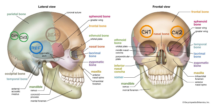
The board is designed to connect dry electrodes and stream real-time data from the EEG channels.
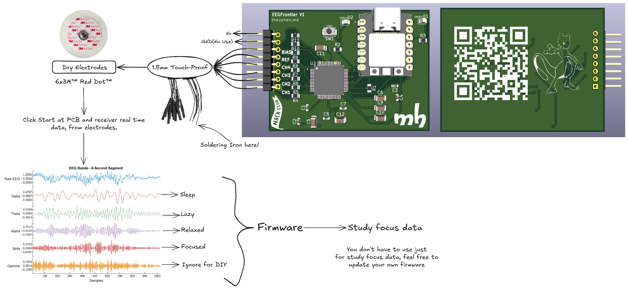
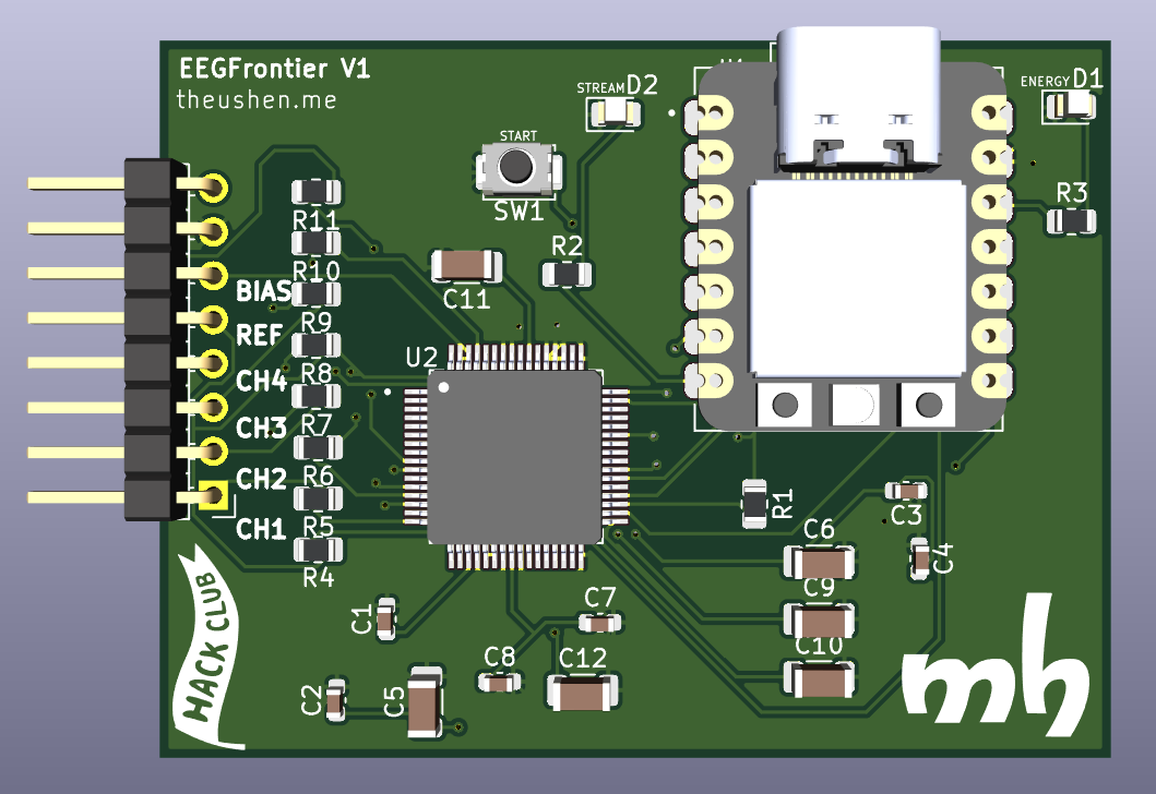
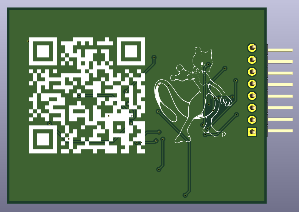
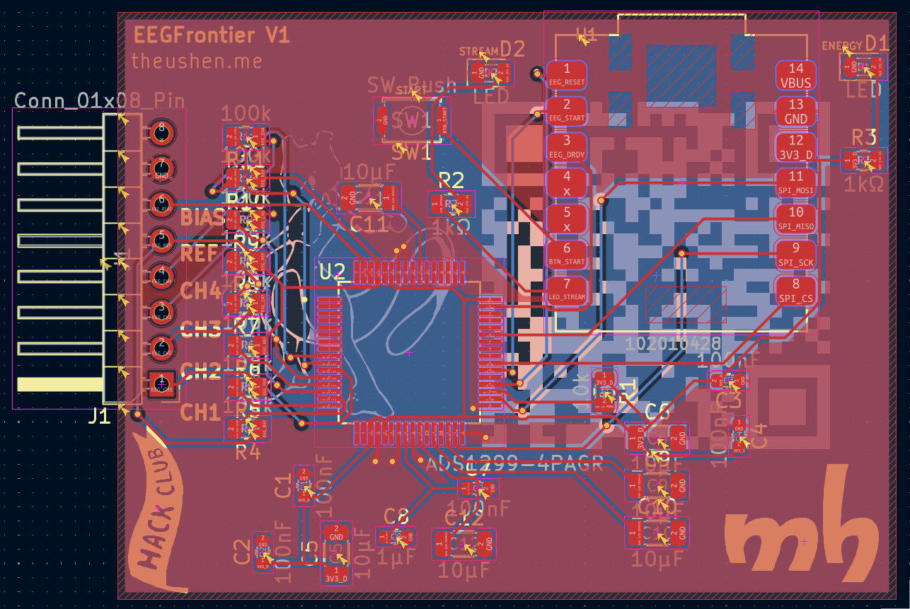
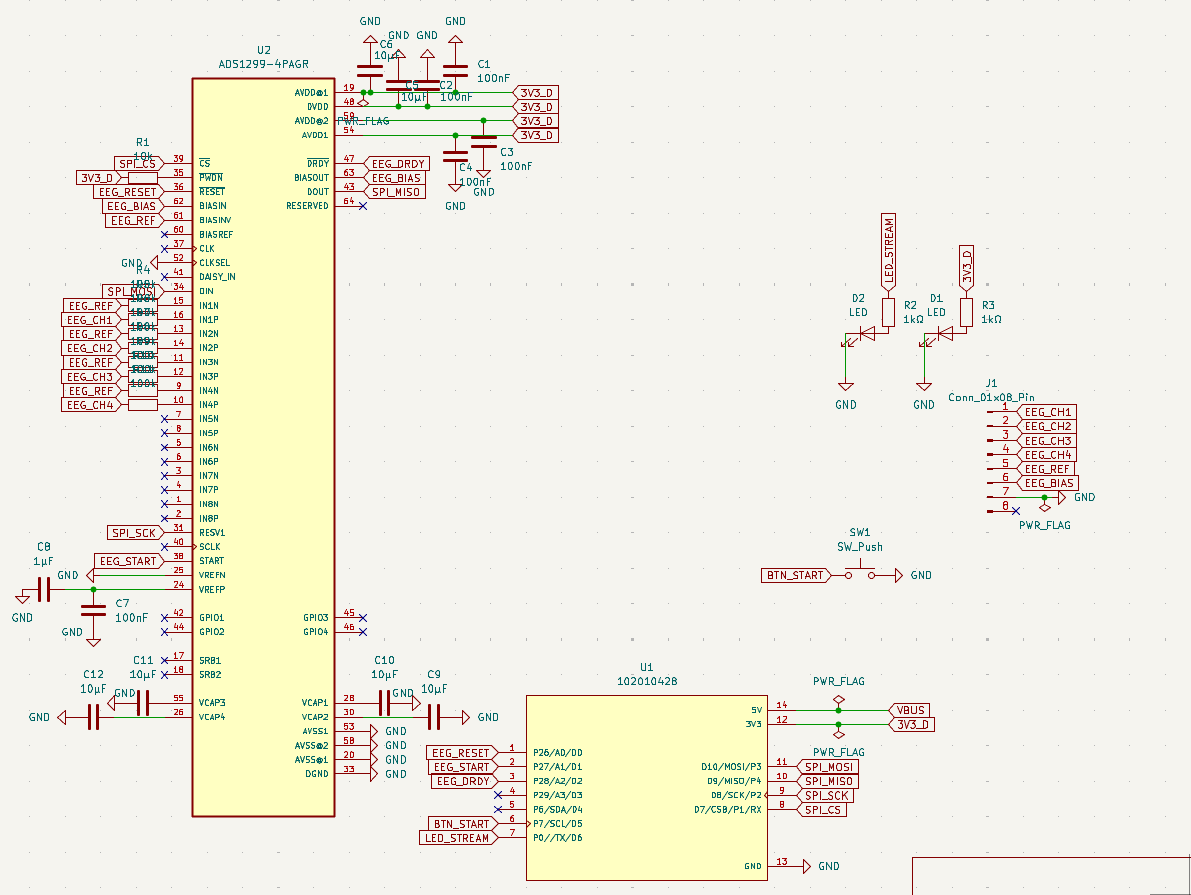
START commandBTN_START)The firmware (in firmware/) provides:
cd firmware
pio run -e xiao_rp2040
Monitor (default baud rate is 921600):
cd firmware
pio device monitor -b 921600HELPINFOSTATSREGSSTARTSTOPMODE BINMODE CSVREINITTEST ONTEST OFFSELFTESTLOFF ONLOFF OFFLOFF STATUSPINGfirmware/ - PlatformIO firmware for XIAO RP2040 + ADS1299assets/ - Images used in this READMEEEGFrontier.kicad_sch / EEGFrontier.kicad_pcb - KiCad project filesPendulum - Host softwarePendulum is the host software suite for EEGFrontier: it reads EEG data over USB, offers a local web dashboard (Reflex), and includes a desktop monitor for real-time focus visualization.
For full setup and usage instructions, see Pendulum/README.md.
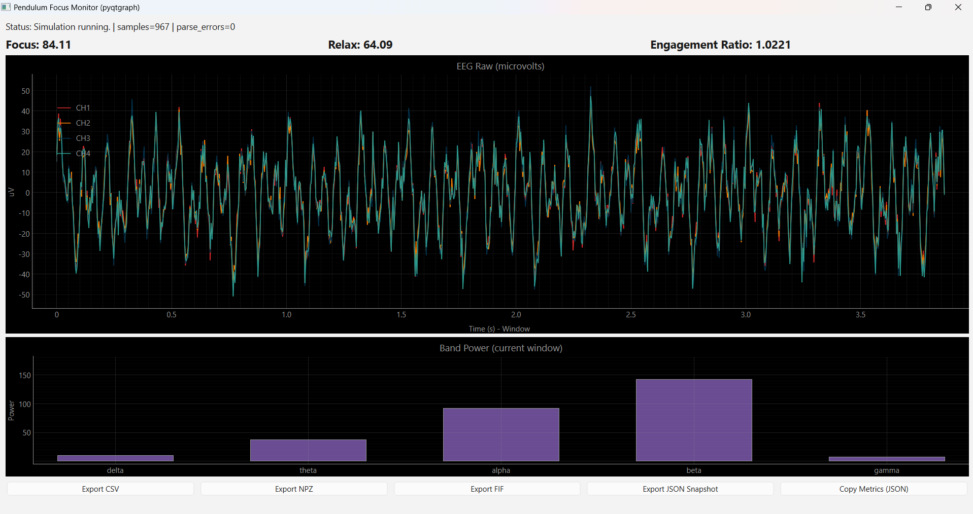
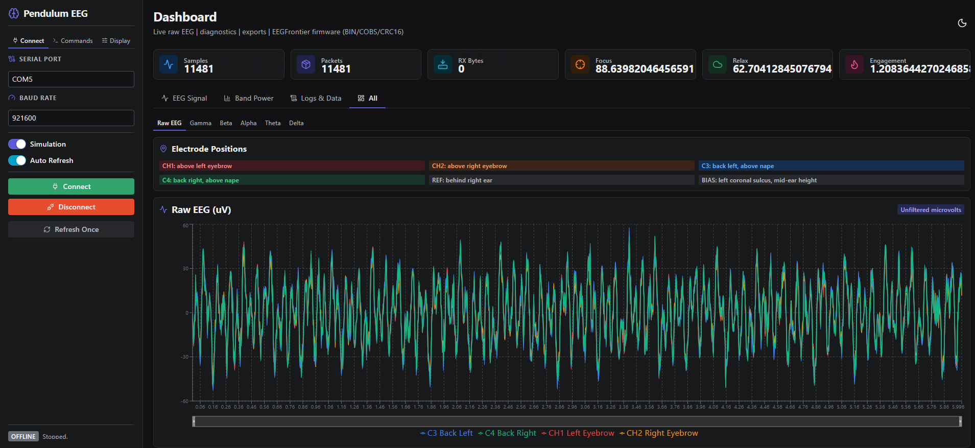
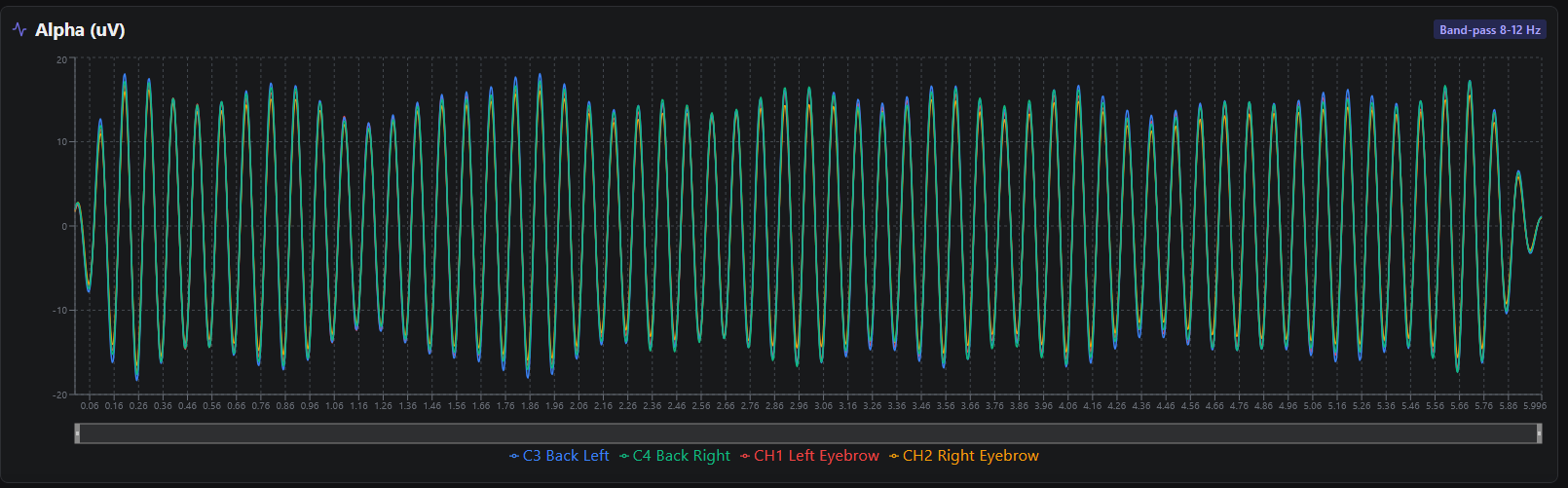
I strongly recommend not attempting to fully hand-solder this PCB.
The board uses fine-pitch components and sensitive analog circuitry, which makes manual soldering difficult and error-prone. Instead, consider ordering the PCB fully assembled from a service such as JLCPCB.
If needed, you can then hand-solder only a few missing components — or none at all if everything is available for assembly.
⚠️ Important Safety Notice
This device interfaces electrically with the human body and must be used with caution.
The author assumes no responsibility for misuse, improper assembly, or unsafe operating conditions.
By using or building this device, you acknowledge that you understand the risks involved in working with bioelectrical signals and accept full responsibility for its use.
This project is not a medical device and is not intended for diagnosis, treatment, or clinical use.
Any data produced by this device should be considered experimental and for educational or research purposes only.
This project is released under the MIT License.
See the LICENSE file for details.
| Qty | Value | Footprint | References |
|---|---|---|---|
| 8 | 100k | Resistor_SMD:R_0805_2012Metric | R4, R5, R6, R7, R8, R9, R10, R11 |
| 6 | 10µF | Capacitor_SMD:C_1206_3216Metric | C5, C6, C9, C10, C11, C12 |
| 5 | 100nF | Capacitor_SMD:C_0603_1608Metric | C1, C2, C3, C4, C7 |
| 4 | LOGO | LOGO | G1, G2, G4, G5 |
| 2 | 1kΩ | Resistor_SMD:R_0805_2012Metric | R2, R3 |
| 2 | LED | LED_SMD:LED_0805_2012Metric | D1, D2 |
| 1 | 102010428 | OPL:MODULE_102010428 | U1 |
| 1 | 10k | Resistor_SMD:R_0805_2012Metric | R1 |
| 1 | 1µF | Capacitor_SMD:C_0603_1608Metric | C8 |
| 1 | ADS1299-4PAGR | OPL:QFP50P1200X1200X120-64N | U2 |
| 1 | Conn_01x08_Pin | Connector_PinHeader_2.54mm:PinHeader_1x08_P2.54mm_Horizontal | J1 |
| 1 | SW_Push | Button_Switch_SMD:SW_Push_SPST_NO_Alps_SKRK | SW1 |
It measures 55 × 41.5 mm and has 2 copper layers, 1.6 mm thick.
33 parts, built around the ADS1299-4PAGR. The full list of its parts is on this page, with links to each part's symbol and footprint where PCBKit's library has them.
From the TheusHen/EEGFrontier repository on GitHub, at the commit this page was made from: the board is PCB/EEGFrontier.kicad_pcb and its schematic SCH/EEGFrontier.kicad_sch. PCBKit opens the board in the browser, with nothing to install.
Its repository publishes it under the MIT licence: you may reuse it on that licence's terms (keep the author's notice, and for a copyleft licence share your changes alike).

ppolGTMonster/RobustEEG_forUHFMRI
Hardware for an Open Source EEG usable in high magnetic Fields

aidanaalund/sleep-wearable
Work on our sleep state tracker wearable headband for ECE Senior Design at UT Austin. Members are Aidan Aalund, Justin Banh, Alex Ho, and Kien Ton. Mentored by Dr. Edison Thomaz.


utof/eeg_ads1299_lab
It is not a finished EEG recorder, a validated PCB, or permission to attach a circuit to a person. The firmware is a board-dependent bench-only starter using the ADS1299's internal test/short circuits.


hoglet67/RGBtoHDMI
Bare-metal Raspberry Pi project that provides pixel-perfect sampling of Retro Computer RGB/YUV video and conversion to HDMI