4 layers18.5 × 18.5 mm

 ThePangel/LodeStone
Don't lose your friends with this GPS LoRa P2P compass!
LodeStonePCB is an open-source printed circuit board by ThePangel, from the ThePangel/LodeStone repository on GitHub, published under the GPL-3.0 licence. It is a 4-layer board of 24 × 48 mm with 8 parts on 64 nets, routed with 231 tracks and 92 vias.
Its parts include 2 ICs and 1 inductor. It belongs with the radio and wireless boards and the ESP32 boards of this library.
Don't lose your friends with this GPS LoRa P2P compass!
Just recently my district's fair started, and between all the crowds and the size of the fairgrounds It's pretty hard to find my friends, especially when we get separated, so with that and me playing a bunch of Minecraft this idea of a Mesh LoRa P2P compass came about.
The name is a reference to the lodestone block in Minecraft which lets you set custom compass targets.
The device consists of 7 components:
The idea is that each node connects to each other individually or in groups, working simultaneously.
Pairing is done by a gesture password consisting of holds and taps, basically a morse code pin. You pair your devices using the same pin, then they handshake, share keys, and establish a connection.
Even if they are not paired (and if enabled), nodes retransmit incoming data packets to other users in the network to increase range.
The compass and map are drawn by taking GPS data from both nodes and the GY-9250 compass and accelerometer to calculate the direction the other node is at.
To optimize battery life and not saturate the airwaves, my system uses a Supply-demand approach. When the node (as a pendant or in the pocket) is still and facing away from the user, it is just listening for either location packets or a request packet. If it receives a location packet, it will update that node's location in memory and nothing else. If it receives a request packet, it will send its own location.
When the node is pulled up to be viewed, it will send a request packet to other nodes to update their location in memory, and a location packet so other nodes update it's location. It will do this at customizable intervals of time while it is being viewed. For signal integrity, the sending node must receive a confirmation packet back to ensure the transmission was successful. This workflow keeps battery usage to a minimum.
I still think it should ping at a set interval to guarante some type of connection, since maybe I can recieve my friends location, but he can't recieve my request so I knever know were he is this could be also tied to speed using the accelerometer, this meaning, the more they move the more they send, if they are still it will default to some configurable interval
We could also tune transmition gain baised on distance, with some headroom of course
To maintain a compact formfactor, interaction with the node will be based on gestures, using the GY-9250 accelerometer and gyro.
Some of this gestures could be:
The menus would be similar to a smart watch.
We can leverage our LoRa connection to send quick preconfigurable messages or write one at that moment using a gesture keyboard or morse code.
In the future I may develop an app to make this easier (tbh just use meshtashtic or meshcore atp), but this is intended for short notification like messages.
I would also like to add an SOS function that sends a signal to all nodes paired, or even if enabled on both ends, all nodes in the network, this will make the nodes flash red and highlight the SOS'ing node.
The PCB is a simple 4 layer PCB that as compactly as possible houses all of the off the shelf components, making it very cheap and easy to assemble, the two outter planes hold traces and GND while the two inner layers are full ground pours, a bunch of vias connect the 4 GNDs to improve RF performance
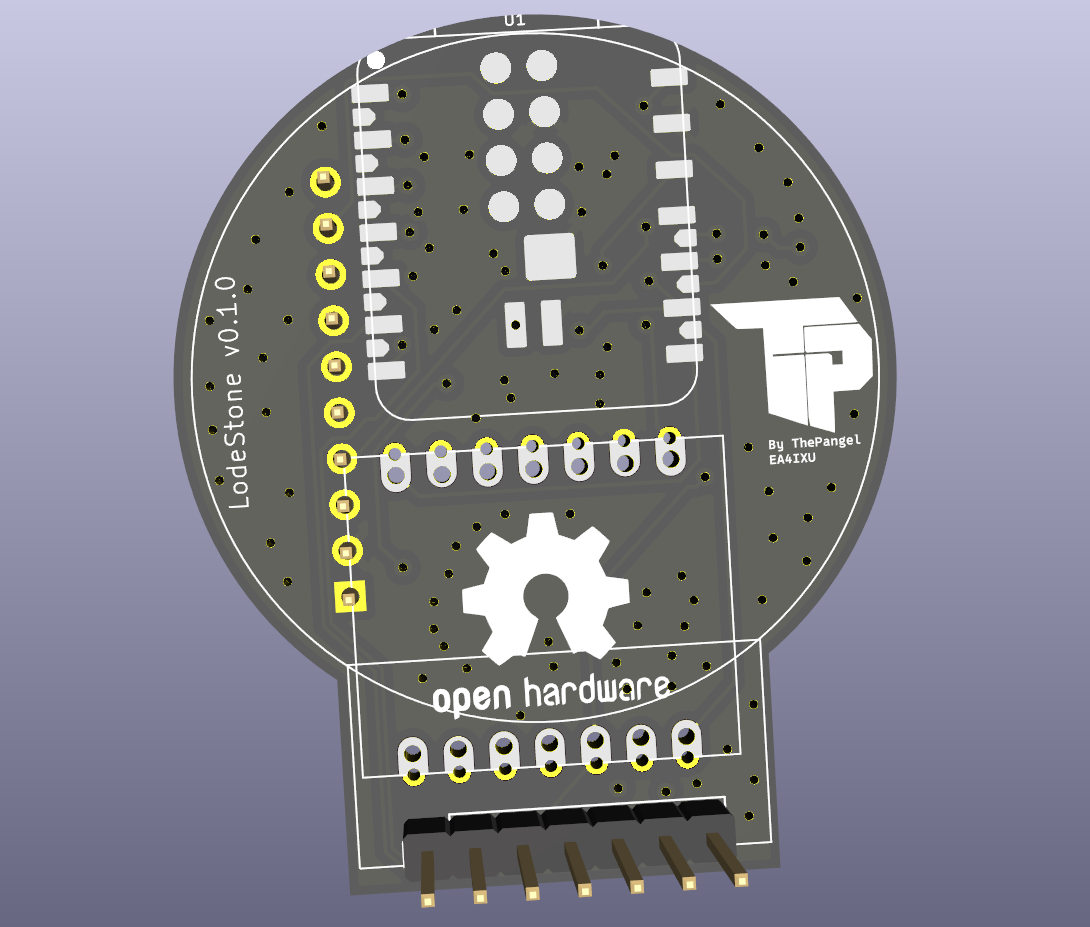
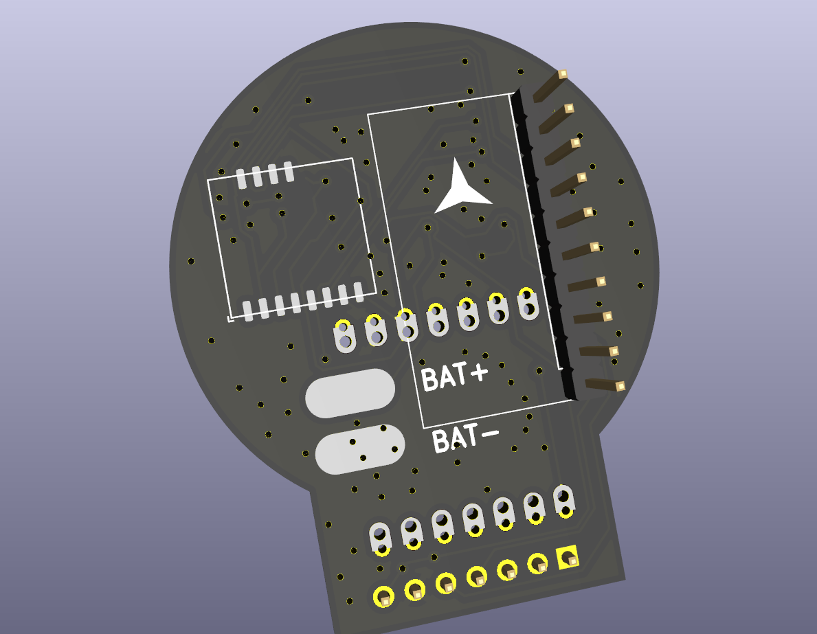
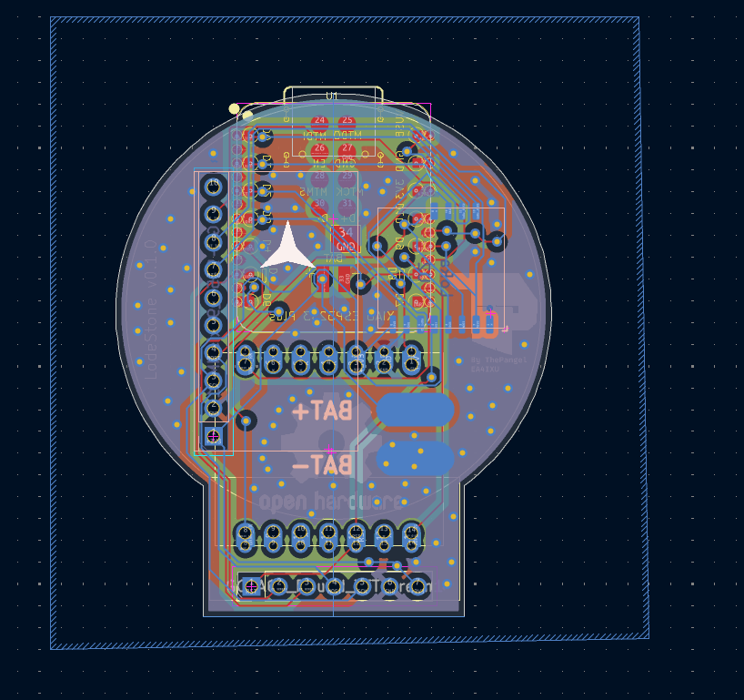
I will make a 3D printed case, as small and tight as possible for it to be portable and comfortable, of course anyone could design their own cases.
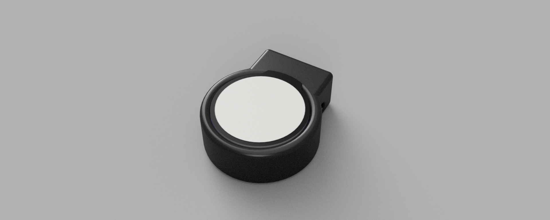
I would like this project to be modular and community focused, so I encourage colaboration integrating for example:
etc.. all from the same modular firmware.
| Qty | Value | Footprint | References |
|---|---|---|---|
| 2 | LOGO | LOGO | G***, G*** |
| 1 | LoRa | LodeStoneFootprint:Wio-SX1262 PCB Package | U2 |
| 1 | XIAO-ESP32-S3-Plus-SMD | LodeStoneFootprint:XIAO-ESP32-S3-Plus-SMD | U1 |
| 1 | ~ | LodeStoneFootprint:XIAO-14P-Add-On | L76K_GNSS_Module1 |
| 1 | ~ | Connector_PinHeader_2.54mm:PinHeader_1x10_P2.54mm_Vertical | GY-9250_9Axis_IMU1 |
| 1 | ~ | Connector_PinHeader_2.54mm:PinHeader_1x07_P2.54mm_Vertical | GC9A01_Round_TFTscreen1 |
The 7 most common of 8 parts.
It measures 24 × 48 mm and has 4 copper layers, 1.6 mm thick.
8 parts. The full list of its parts is on this page, with links to each part's symbol and footprint where PCBKit's library has them.
From the ThePangel/LodeStone repository on GitHub, at the commit this page was made from: the board is LodeStonePCB/LodeStonePCB.kicad_pcb and its schematic LodeStonePCB/LodeStonePCB.kicad_sch. PCBKit opens the board in the browser, with nothing to install.
Its repository publishes it under the GPL-3.0 licence: you may reuse it on that licence's terms (keep the author's notice, and for a copyleft licence share your changes alike).


rjwalters/kicad-tools
Standalone Python tools for parsing and manipulating KiCad schematic and PCB files


ras-marques/ImmersiveGloves
I want to share how I am making vr gloves using 2 Tundra Trackers, 2 interface boards and 12 inertial sensors.


