
2 layers108 × 122 mm
Myolo
nico-entz/MyoloV2
A simple muon/particle detector based on STM32 (BluePill), Scintillators and MicroFC SiPMS
67 parts8MIT

 ThemisEfth/fNMES-Technical-Guide
This repository contains the Python script for a graphical user interface (GUI) designed to control electrical stimulators via Arduino boards.
Dac controller is an open-source printed circuit board by ThemisEfth, from the ThemisEfth/fNMES-Technical-Guide repository on GitHub, published under the MIT licence. It is a 2-layer board with 31 parts on 47 nets, routed with 184 tracks and 10 vias.
It is built around the LM6172IM. Its parts include 11 capacitors, 7 resistors, 3 ICs, 3 connectors and 1 inductor. It belongs with the audio and music and interfaces and adapters boards and the AVR (ATmega, ATtiny) boards of this library.
This repository contains the Python script for a graphical user interface (GUI) designed to control electrical stimulators via Arduino boards, facilitating precise adjustment of electrical stimulation parameters. This repository accompanies the paper titled: Computer-controlled electrical stimulation of facial muscles by facial neuromuscular electrical stimulation (fNMES): Hardware and software solutions.
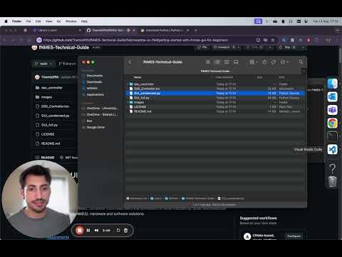
The GUI is developed using Python 3.8.5 and utilizes the tkinter package for the interface. Additional Python modules required are:
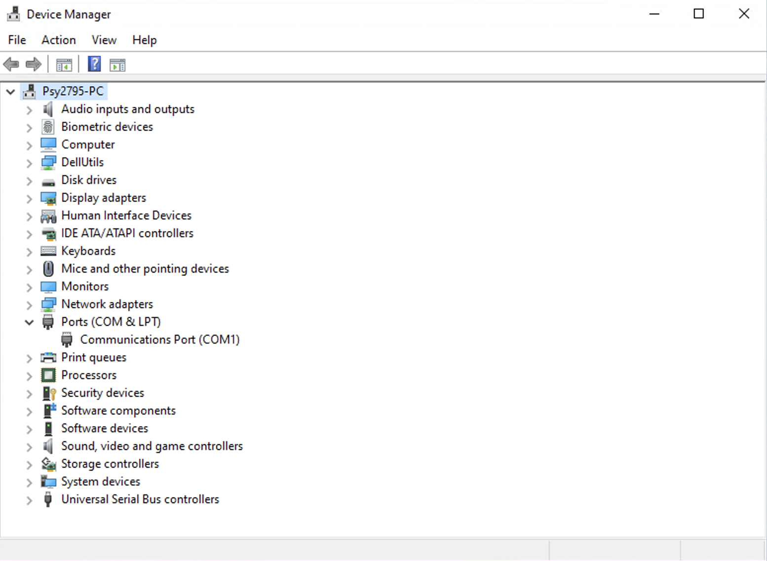
serial: for sending serial commands to Arduinotime: to incorporate delays in commands using time.sleepEnsure the Arduino is set with a BaudRate of 19200. Connection ports differ based on the operating system:
ls /dev/tty* and note the port number listed for /dev/ttyUSB* or /dev/ttyACM** here.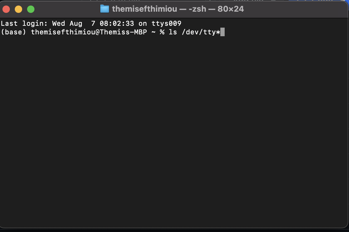
The GUI interfaces with the Arduino by sending Hex commands to trigger specific actions in the firmware (DS5 controlled, built by Andreas Gartus, 2020).
99 for start)0 (e.g., xFF for start)255 (0xFF): Initiates device, sets default settings, and opens the port for commands.99 (0x63): Blinks the display as a command test (do not use continuously).69 (0x45) + 1: Turns the display off.68 (0x44) + 0: Turns the display on.78 (0x4E): Resets pulse count to zero.65 (0x41): Displays current settings on Arduino.80 (0x50): Begins pulse sequence.33 (0x21): Emergency stop for pulse sequence.98 (0x62): Set pulse mode to bipolar.97 (0x61): Set pulse mode to monopolar with OpAmp.96 (0x60): Set pulse mode to monopolar without OpAmp.To use the fNMES-GUI, you'll need a basic setup and understanding of how to run Python scripts. Here's a step-by-step guide to get you started:
Before running the GUI, make sure you have the following:
tkinter, serial, and time modules are installed. You can install any required modules using pip. For example:
pip install pyserialCode button and select Download ZIP, or clone the repository using:
git clone git@github.com:ThemisEfth/fNMES-Technical-Guide.git](https://github.com/ThemisEfth/fNMES-Technical-Guide)There are two types of GUIs available: a condensed version and a full version.
The condensed GUI focuses on simplifying the user interface by reducing the number of input fields and emphasizing the use of milliseconds over microseconds for input parameters. This version is recommended for most users due to its simplicity and ease of use.
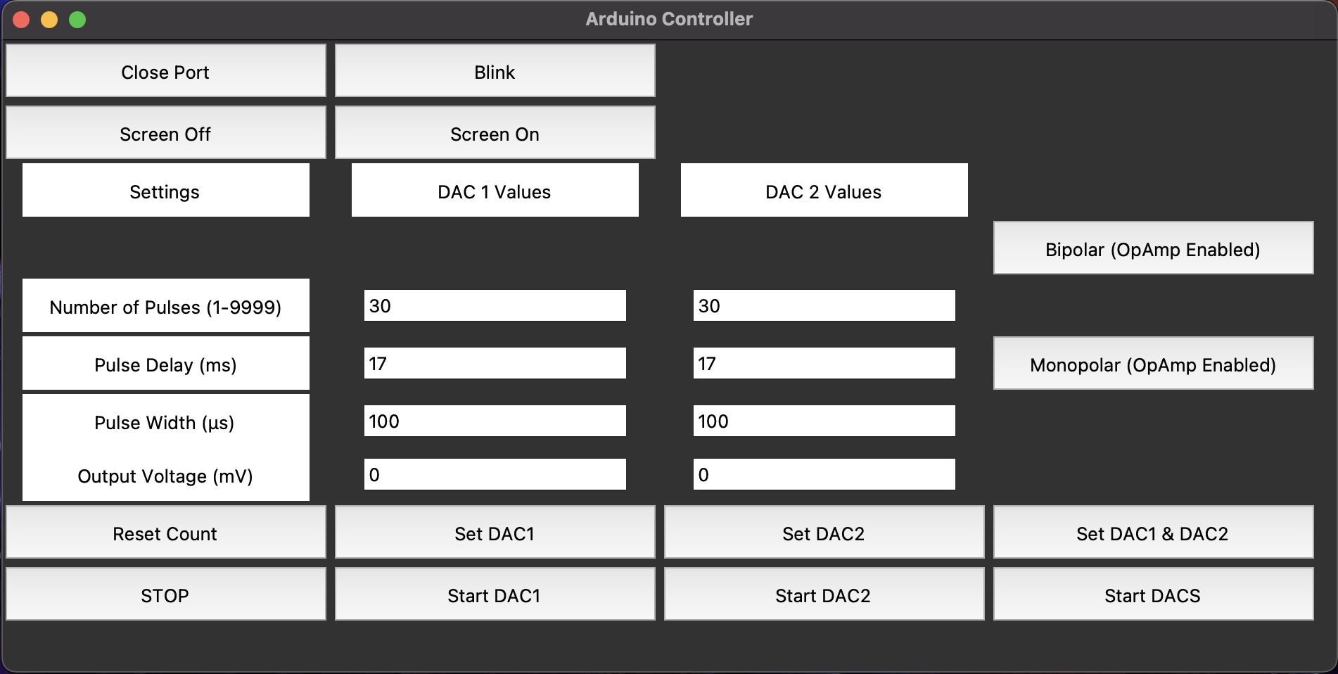
The full GUI provides a more comprehensive interface with additional input fields, allowing for more detailed control over the stimulation parameters. This version includes inputs for both milliseconds and microseconds, giving users more flexibility in their settings.
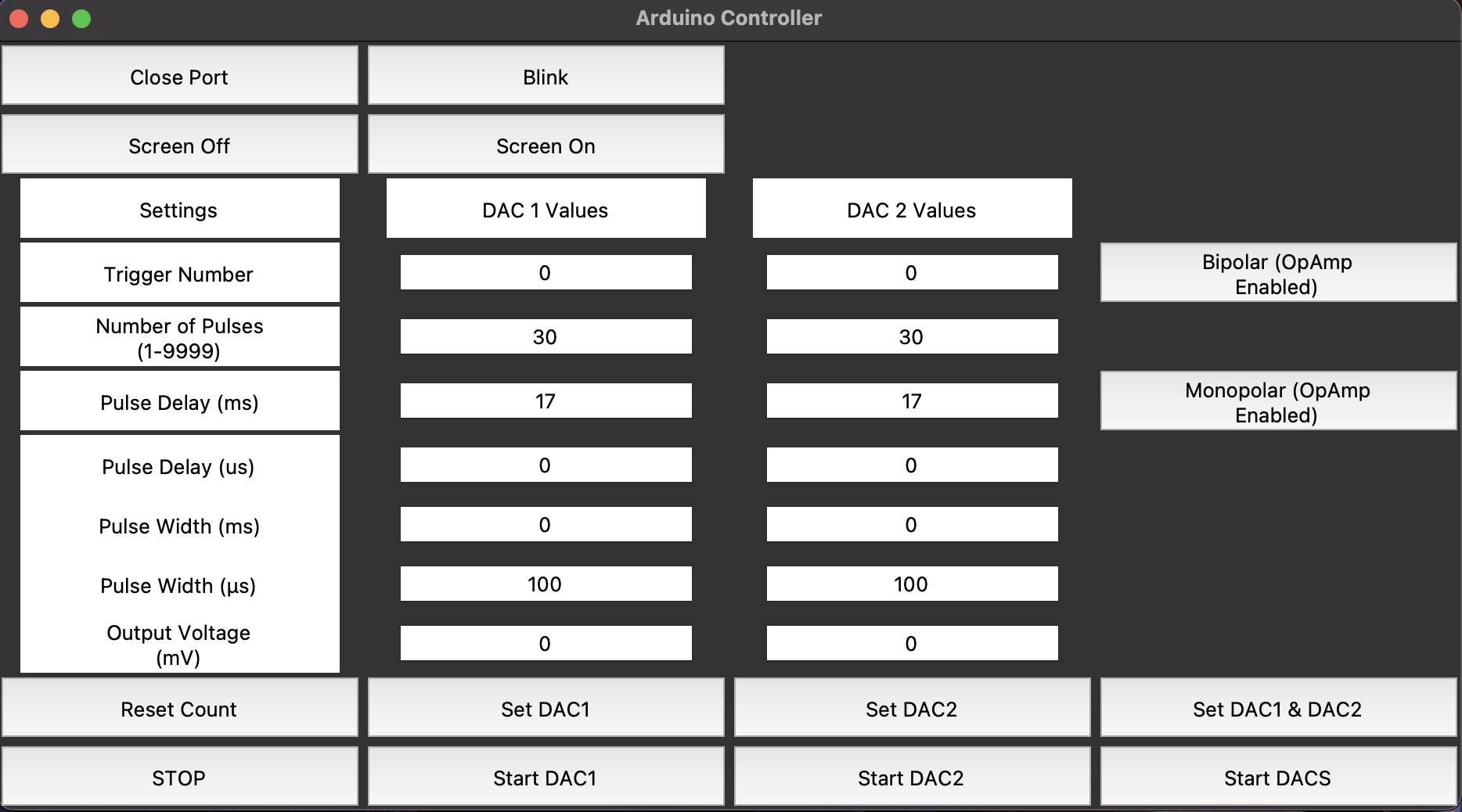
To switch between the GUIs, simply use the corresponding Python script provided in the repository for each version.
Once you have Python and the script on your local machine, you can run the script using one of the following methods:
Before running the GUI, you need to configure the script to communicate with the correct Arduino port:
arduino = serial.Serial('COM3', 19200)'COM3' with the port you identified earlier.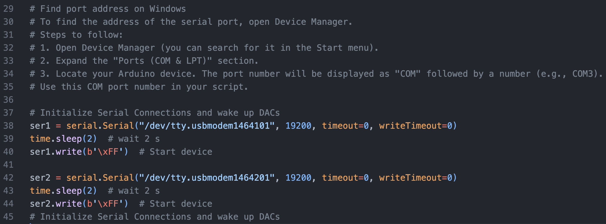
After configuring the port, run the script in the IDE.
Alternatively, you can run the Python file in the terminal/command line:
cd path/to/your/scriptpython fNMES_GUI.pyThe GUI should launch, allowing you to interact with the Arduino-connected stimulator.
The repository also includes the Arduino .ino file, which is essential for the operation of the fNMES system. This firmware enables the Arduino to:
The Arduino firmware is designed to be flexible, allowing researchers to tailor the electrical stimulation parameters to their specific experimental needs. It facilitates the delivery of precise electrical pulses to facial muscles, making it a valuable tool for studying facial feedback effects and their neurological basis.
To load the .ino firmware onto your Arduino, follow these steps:
Once the firmware is successfully uploaded, your Arduino is ready to communicate with the Python GUI and execute the electrical stimulation commands.
The dac_controller subfolder contains the necessary files for building and configuring the DAC (Digital-to-Analog Converter) controller. This includes both the Arduino code and the schematics for assembling the DAC.
dac_controller SubfolderTMR0521_Library.kicad_sym: KiCad symbol library file.dac_controller.kicad_pcb: KiCad PCB design file.dac_controller.kicad_prl: KiCad project file.dac_controller.kicad_pro: KiCad project file.dac_controller.kicad_sch: KiCad schematic file.dac_controller.net: KiCad netlist file.dac_controller_pcb_1.1.pdf: PDF file of the PCB layout.dac_controller_schematic_1.1.pdf: PDF file of the schematic diagram.sym-lib-table: Symbol library table file.These files provide all the necessary information to build the DAC controller, which is used to control the analogue output signals for the fNMES system. Below are the details on how to use the provided files to assemble and configure the DAC controller.
dac_controller.kicad_pro project file in KiCad to access the full design of the DAC controller.dac_controller.kicad_sch file contains the schematic diagram, which shows the circuit design.dac_controller.kicad_pcb file includes the layout of the PCB, which is used to manufacture the physical circuit board.dac_controller_schematic_1.1.pdf file provides a PDF version of the schematic diagram for easy reference.dac_controller_pcb_1.1.pdf file offers a PDF version of the PCB layout, which can be used to understand the physical placement of components on the board.TMR0521_Library.kicad_sym file contains the symbols for components used in the DAC controller design.dac_controller.net file provides the netlist for the DAC controller, which is used to link the schematic components with the PCB layout.sym-lib-table file helps KiCad locate the component symbols needed for the design.Follow these steps to build the DAC controller:
dac_controller.kicad_pro project file.dac_controller.kicad_sch file in KiCad’s Eeschema tool to review the schematic diagram.dac_controller.kicad_pcb file in KiCad’s PCBnew tool to review the PCB layout.dac_controller_schematic_1.1.pdf and dac_controller_pcb_1.1.pdf files for guidance.The provided Arduino code and hardware schematics enable the integration of these parameters into the fNMES setup, allowing for precise and reproducible facial muscle stimulation in experimental settings.
This project is licensed under the MIT License - see the LICENSE.md file for details. This license allows you to use, modify, and distribute the software as you see fit.
| Qty | Value | Footprint | References |
|---|---|---|---|
| 3 | 10n | Capacitor_THT:C_Disc_D3.0mm_W1.6mm_P2.50mm | C7, C9, C11 |
| 2 | 100R | Resistor_THT:R_Axial_DIN0207_L6.3mm_D2.5mm_P10.16mm_Horizontal | R3, R4 |
| 2 | 100n | Capacitor_THT:C_Disc_D3.0mm_W1.6mm_P2.50mm | C3, C4 |
| 2 | 2u2 | Capacitor_THT:CP_Radial_Tantal_D4.5mm_P2.50mm | C6, C8 |
| 1 | 100n | Capacitor_THT:C_Disc_D4.3mm_W1.9mm_P5.00mm | C5 |
| 1 | 10k | Resistor_THT:R_Axial_DIN0204_L3.6mm_D1.6mm_P2.54mm_Vertical | R6 |
| 1 | 10k | Resistor_THT:R_Axial_DIN0207_L6.3mm_D2.5mm_P5.08mm_Vertical | R1 |
| 1 | 10k | Resistor_THT:R_Axial_DIN0207_L6.3mm_D2.5mm_P2.54mm_Vertical | R2 |
| 1 | 10u | Capacitor_THT:CP_Radial_D5.0mm_P2.50mm | C1 |
| 1 | 20k | Potentiometer_THT:Potentiometer_Bourns_3005_Horizontal | RV1 |
| 1 | 22R | Resistor_THT:R_Axial_DIN0207_L6.3mm_D2.5mm_P7.62mm_Horizontal | R5 |
| 1 | 22u | Capacitor_THT:CP_Radial_D5.0mm_P2.50mm | C2 |
| 1 | 2p2 | Capacitor_THT:C_Disc_D4.3mm_W1.9mm_P5.00mm | C10 |
| 1 | 3u3 | Inductor_THT:L_Axial_L5.3mm_D2.2mm_P10.16mm_Horizontal_Vishay_IM-1 | L1 |
| 1 | 47R | Resistor_THT:R_Axial_DIN0207_L6.3mm_D2.5mm_P7.62mm_Horizontal | R7 |
| 1 | Analog Output | Connector_Molex:Molex_KK-254_AE-6410-02A_1x02_P2.54mm_Vertical | J3 |
| 1 | Arduino_Uno_R3_SMD_Shield | PCM_arduino-library:Arduino_Uno_R3_Shield | A1 |
| 1 | Filter DAC | Connector_PinHeader_2.54mm:PinHeader_1x02_P2.54mm_Vertical | JP1 |
| 1 | Filter Output | Connector_PinHeader_2.54mm:PinHeader_1x02_P2.54mm_Vertical | JP4 |
| 1 | Gain = 1 | Connector_PinHeader_2.54mm:PinHeader_1x02_P2.54mm_Vertical | JP3 |
| 1 | I2C Display | Connector_Molex:Molex_KK-254_AE-6410-04A_1x04_P2.54mm_Vertical | J1 |
| 1 | LM6172 | Package_DIP:DIP-8_W7.62mm | U3 |
| 1 | LTC1257 | Package_DIP:DIP-8_W7.62mm | U2 |
| 1 | Negative bias | Connector_PinHeader_2.54mm:PinHeader_1x03_P2.54mm_Vertical | JP2 |
| 1 | TMR-0521 | Converter_DCDC:Converter_DCDC_TRACO_TMR-xxxx_THT | U1 |
| 1 | Trigger Output | Connector_Molex:Molex_KK-254_AE-6410-03A_1x03_P2.54mm_Vertical | J2 |
31 parts, built around the LM6172IM. The full list of its parts is on this page, with links to each part's symbol and footprint where PCBKit's library has them.
From the ThemisEfth/fNMES-Technical-Guide repository on GitHub, at the commit this page was made from: the board is dac_controller/dac_controller.kicad_pcb and its schematic dac_controller/dac_controller.kicad_sch. PCBKit opens the board in the browser, with nothing to install.
Its repository publishes it under the MIT licence: you may reuse it on that licence's terms (keep the author's notice, and for a copyleft licence share your changes alike).
nico-entz/MyoloV2
A simple muon/particle detector based on STM32 (BluePill), Scintillators and MicroFC SiPMS

nuclearfutureslab/ibxII-hardware
Hardware for IBX ][ - nuclear warhead verification with an Apple II

HarshitRaj3007/EDL2024
Repository for our EDL project in year 2024. RRAM Characterization using FPGA.

odegroote/FGControlPCB
KiCAD 9.0 project for a 2 layer PCB design of a 2 channel functiongenerator

phooky/Flat-SIP
An attempt to make a flat, relatively low-cost recreation of the Sandin Image Processor.


joeycastillo/Sensor-Watch
A board replacement for the classic Casio F-91W wristwatch