2 layers60 × 30 mm

 thehackbat/defcon32_badge13
Badge designed for DEFCON32
Defcon32 badge is an open-source printed circuit board by thehackbat, from the thehackbat/defcon32_badge repository on GitHub, published under the GPL-3.0 licence. It is a 2-layer board of 60 × 100 mm with 50 parts on 29 nets, routed with 277 tracks and 30 vias.
It is built around the ESP32-C3-WROOM-02-H4, AMS1117-3.3 and WS2812B. Its parts include 11 resistors, 8 switches, 6 capacitors, 6 diodes and 3 connectors. It belongs with the lEDs and displays and radio and wireless boards and the ESP32 and RISC-V boards of this library.


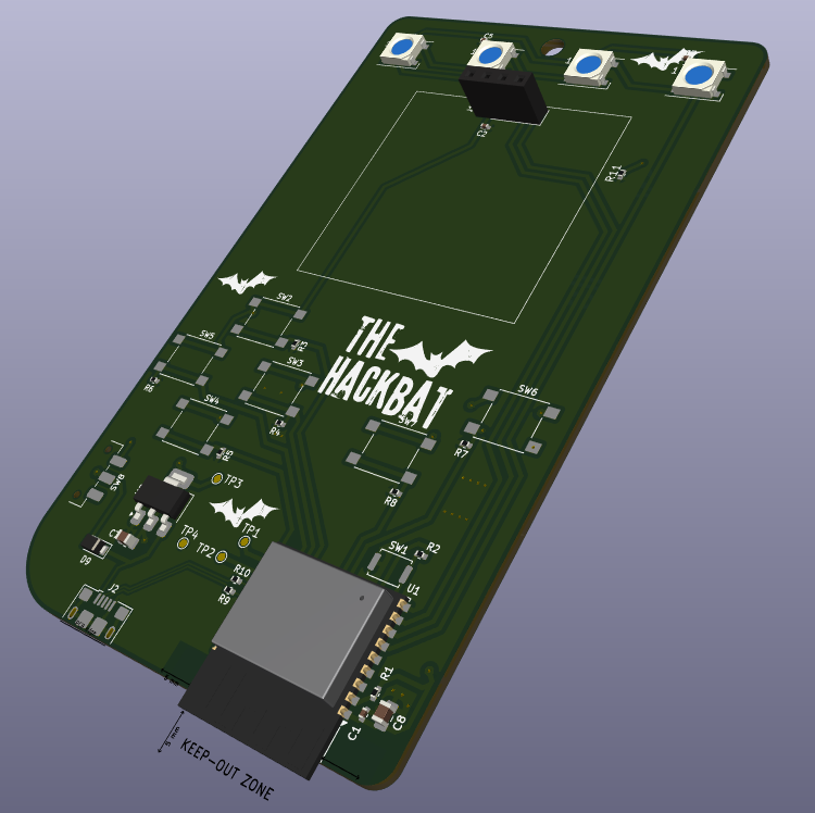
The Hackbat BAdge has been designed specially for DEFCON32. This badge features the ESP32C3 microcontroller with WIFI and Bluetooth. The board also has LEDs, and an OLED Display to show information.
If you received your badge at DEFCON, read this!!
The microcontroller used in the Hackbat Badge is the ESP32-C3 from Espressif. The format used is the WROOM. This microcontroller features a RISC-V single-core processor, WIFI at 2.4GHz IEEE 802.11b/g/n-compliant, Bluetooth LE 5.0, and a bunch of peripherals like SPI, I2C, UART...
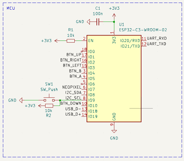
This microcontroller can be programmed using either the Arduino IDE or the official ESP-IDF.
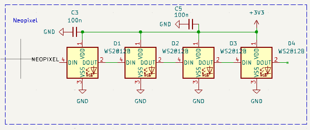
LED are a must in any badge. The Hackbat Badge has 4 smart LEDs, the WS2812. This LED hs a controller integrated so you can choos the color using a serial protocol. The best of these LED is that you can conenct many of them in series, and send different commands to each one.
The layout of the board is designed to looks like an old GAMEBOY, havning 6 push-buttons, and the OLED display. The microcontroller is located in the bottom part of the board, like the USB connector. The backside of the Badge is reserved for a case with three AA cells.
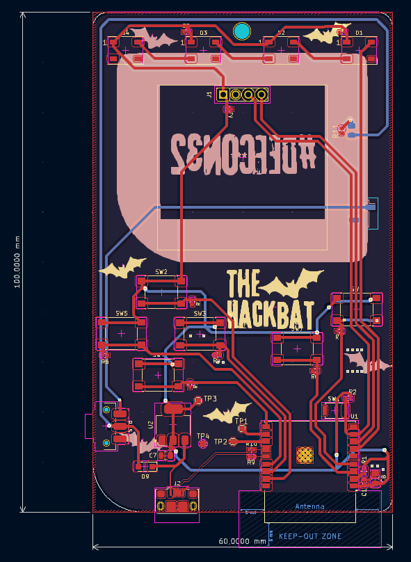
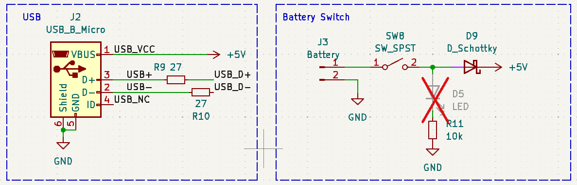
This board have been designed in 2 days to be sure that it will be ready for DEFCON32, but in many cases being the designs fast means errors. If you recevived your Hackbat Badge at DEFCON, the diode D9 is not in its correct place. This diode keep the battery disconnected when the USB is connected, but in the first version of the board this diode is placed in the battery USB side, so since the 5V of the USb are greater than the 4.5 volts of the battery, the USB is conencted directly to the battery. This version have this issue fixed.
The HackBat Badge is open-source, so you can use the output files to manufacture your own in JLCPCB. You just need to compress the production_files directory, and upload it to JLCPCB.
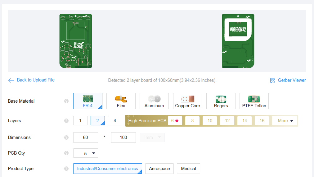
Remember to change the Surface Finish to LeadFree HASL to make your board ROHS compliant. Also, the original board uses a Black PCB color, so if you want to keep your Hackbat like the original, you can select this color to be sure that the silkscreen is seen correctly.
Then you have to add the PCB Assembly service and upload the centroid file, and the BOM.
In a few days, you will receive your board at home.
| Qty | Value | Footprint | References |
|---|---|---|---|
| 9 | 10k | Resistor_SMD:R_0402_1005Metric | R1, R2, R3, R4, R5, R6, R7, R8, R11 |
| 6 | LOGO | IMG:bat | G***, G***, G***, G***, G***, G*** |
| 6 | SW_Push | Button_Switch_SMD:SW_Push_1P1T_NO_6x6mm_H9.5mm | SW2, SW3, SW4, SW5, SW6, SW7 |
| 4 | 100n | Capacitor_SMD:C_0402_1005Metric | C1, C2, C3, C5 |
| 4 | TestPoint | TestPoint:TestPoint_Pad_D1.0mm | TP1, TP2, TP3, TP4 |
| 4 | WS2812B | LED_SMD:LED_WS2812B_PLCC4_5.0x5.0mm_P3.2mm | D1, D2, D3, D4 |
| 2 | 1u | Capacitor_SMD:C_0805_2012Metric | C7, C8 |
| 2 | 27 | Resistor_SMD:R_0402_1005Metric | R9, R10 |
| 1 | AMS1117-3.3 | Package_TO_SOT_SMD:SOT-223-3_TabPin2 | U2 |
| 1 | Battery | Connector_PinSocket_2.54mm:PinSocket_1x02_P2.54mm_Vertical_SMD_Pin1Left | J3 |
| 1 | Conn_01x04_Pin | Connector_PinSocket_2.54mm:PinSocket_1x04_P2.54mm_Vertical | J1 |
| 1 | D_Schottky | Diode_SMD:Nexperia_CFP3_SOD-123W | D9 |
| 1 | ESP32-C3-WROOM-02 | RF_Module:ESP32-C3-WROOM-02 | U1 |
| 1 | LED | LED_SMD:LED_0805_2012Metric | D5 |
| 1 | LOGO | IMG:defcon_hashtag | G*** |
| 1 | LOGO | IMG:gb_screen | G*** |
| 1 | LOGO | IMG:hackbat_logo | G*** |
| 1 | MountingHole | MountingHole:MountingHole_3.2mm_M3 | H1 |
| 1 | SW_Push | Button_Switch_SMD:SW_Push_SPST_NO_Alps_SKRK | SW1 |
| 1 | SW_SPST | Button_Switch_SMD:SW_SPDT_CK_JS102011SAQN | SW8 |
| 1 | USB_B_Micro | Connector_USB:USB_Micro-B_Amphenol_10118193-0001LF_Horizontal | J2 |
It measures 60 × 100 mm and has 2 copper layers, 1.6 mm thick.
50 parts, built around the ESP32-C3-WROOM-02-H4, AMS1117-3.3 and WS2812B. The full list of its parts is on this page, with links to each part's symbol and footprint where PCBKit's library has them.
From the thehackbat/defcon32_badge repository on GitHub, at the commit this page was made from: the board is kicad/defcon32_badge.kicad_pcb and its schematic kicad/defcon32_badge.kicad_sch. PCBKit opens the board in the browser, with nothing to install.
Its repository publishes it under the GPL-3.0 licence: you may reuse it on that licence's terms (keep the author's notice, and for a copyleft licence share your changes alike).

oltdaniel/PCB_deskDisplay
a small esp32-c3 PCB for an I²C display, NeoPixel and Button for smart home stuff.

ssi51/MCC25-Badge
Official repository for the MCC 25' Badge. An open-source, ESP32-C3 powered badge featuring WiFi, BLE and a retro-gaming interface.


khill25/Dreamdrive
Open source Retro Rom Carts and ODEs by Dreamcraft Industries


joshitha-c/rf_detector
A portable, custom-built RF signal scanner and power detector designed for knowing wireless signals, measuring signal strength and can be used to be safe.