2 layers115 × 75 mm

 tguyenn/digital-synthesizer
Embedded Lab Final Project (UT ECE445L)
Main boardv2 is an open-source printed circuit board by tguyenn, from the tguyenn/digital-synthesizer repository on GitHub. It is a 2-layer board with 123 parts on 113 nets.
It is built around the RP2040, LM321LVIDBVR-TP and AT25FF161A-SHN-B, with the SN74LV1T34DBVR-TP, TPD3E001DRLR and ABM8-272-T3 among its other parts. Its parts include 31 capacitors, 28 resistors, 16 connectors, 8 ICs and 8 diodes. It belongs with the RP2040 boards of this library.


Brought to you by...
@jeffchang0
@MorrisYLin
@zaarabilal
@tguyenn
We decided to build a digital synthesizer/piano for our final project in UT Austin's Embedded Lab Class! We thought a piano was a great idea since we all love music, and a digital synthesizer presented a good deal of electrical, mechanical, and programming challenges.
Our digital piano consists of
1.) A main controller board
2.) A series of peripheral boards
3.) Piano keys with magnets
4.) Piano enclosure
... all from scratch!
Here's a clip of our project (Rev A) in action, credit to @jeffchang0:
[!IMPORTANT] Please enable audio and applaud the
mouthcamerawork for the full demonstration!
Figuring out requirements is by far the most important part of a project! Of course you have to know what you are building before you build it :)
We knew we wanted to make a piano of a larger scale, so we had to figure out how to seamlessly connect a lot of keys together.
After some thinking and debate, we came down to this diagram for our overall system design:
We opted to have a main controller board daisy-chained with a series of peripheral boards. This main board would also be connected to user interfaces like an LCD, digital rotary encoders, and an addressable LED strip.
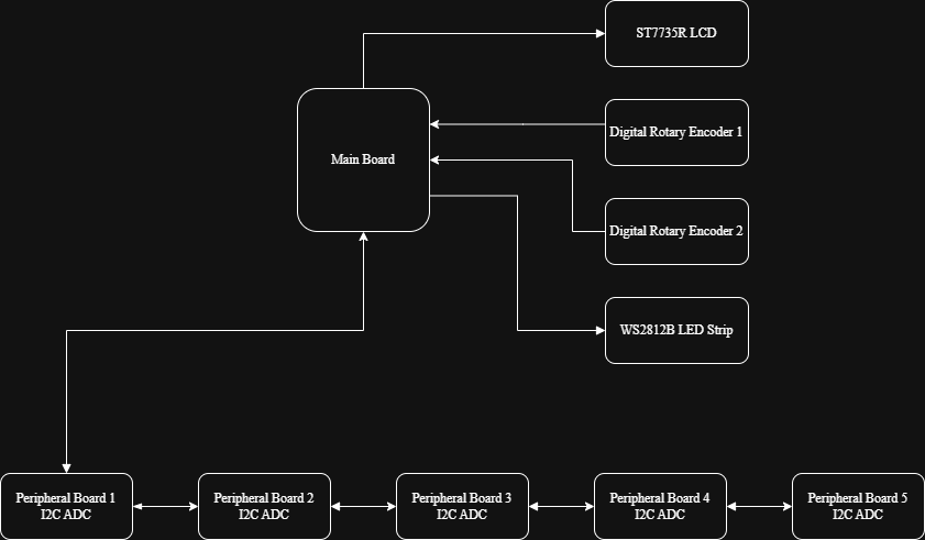 |
| System Plan Diagram |
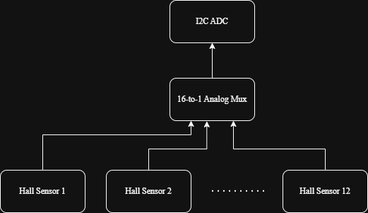 |
| Peripheral Board Plan Diagram |
To give some insight into what this came to be, here is a picture of our daisy-chained peripheral boards (sharpie for scale):
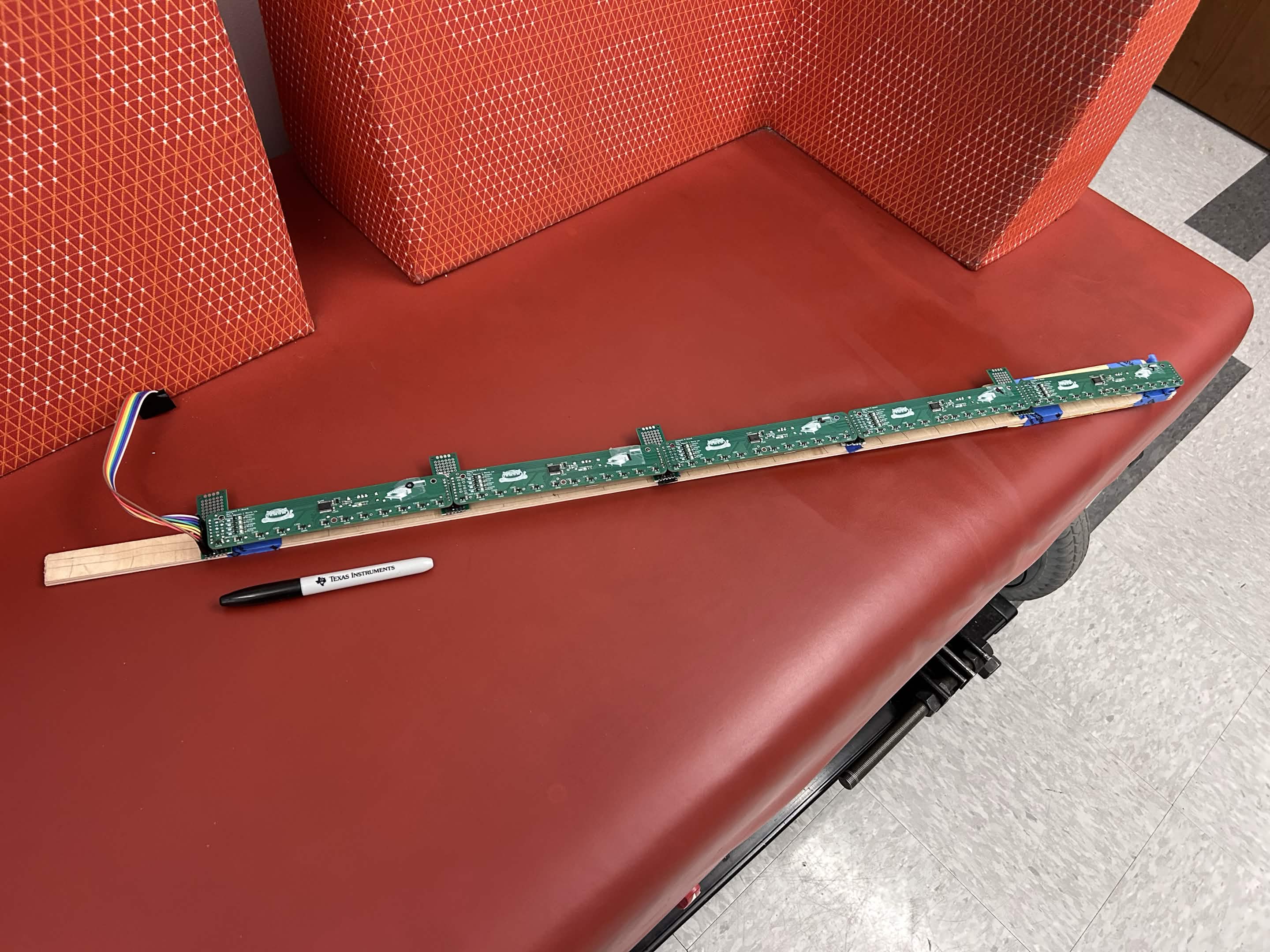 |
| Extra Extra Long PCB |
Once we had planned out the high-level details of the project, it was time to figure out what electrical connections needed to be made. First, it was time to go window shopping and datasheet diving on Mouser to figure out what we were even working with.
Once we had picked out all our parts, we drew out the schematic (and all of the relevant subsheets):
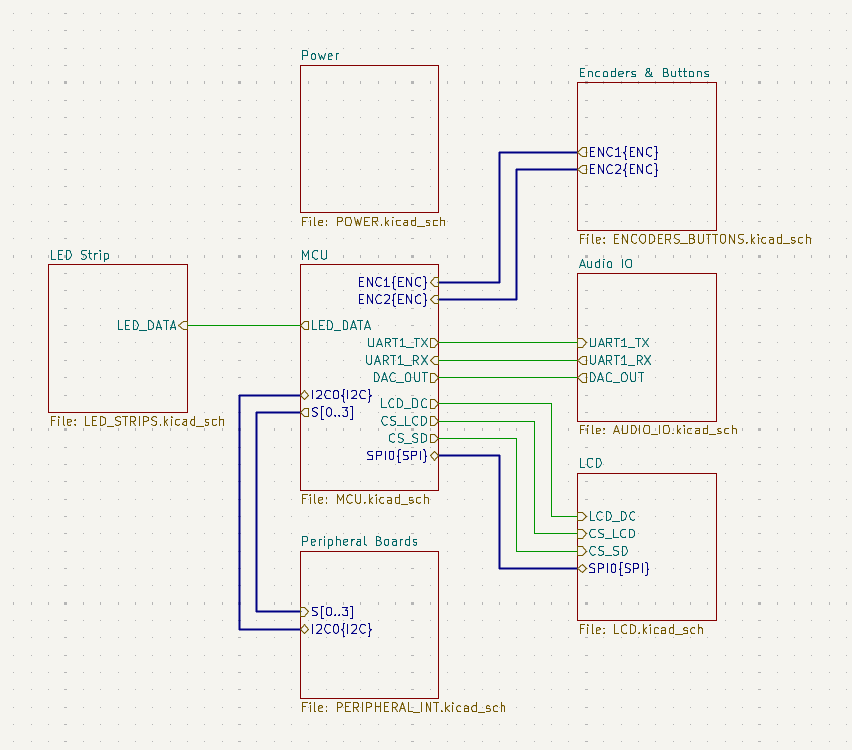 | 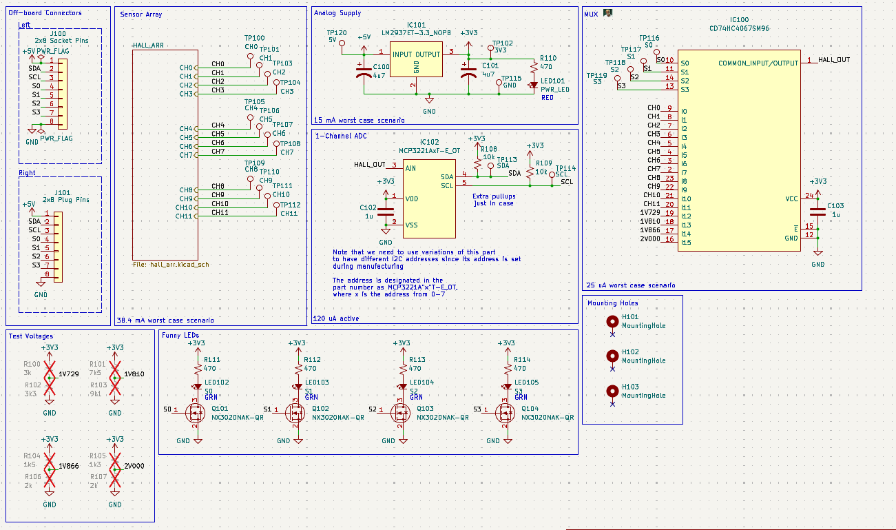 |
| Rev A - Main (Left) and Peripheral (Right) Schematics | |
After verifying the schematic, we moved onto laying out the PCB itself:
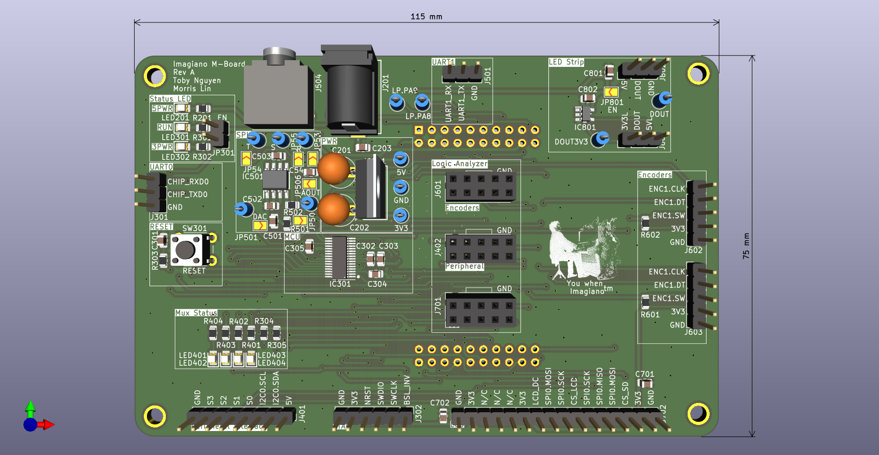 | 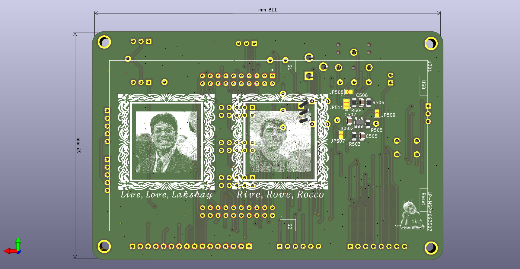 |
| Rev A - Front and back main board | |
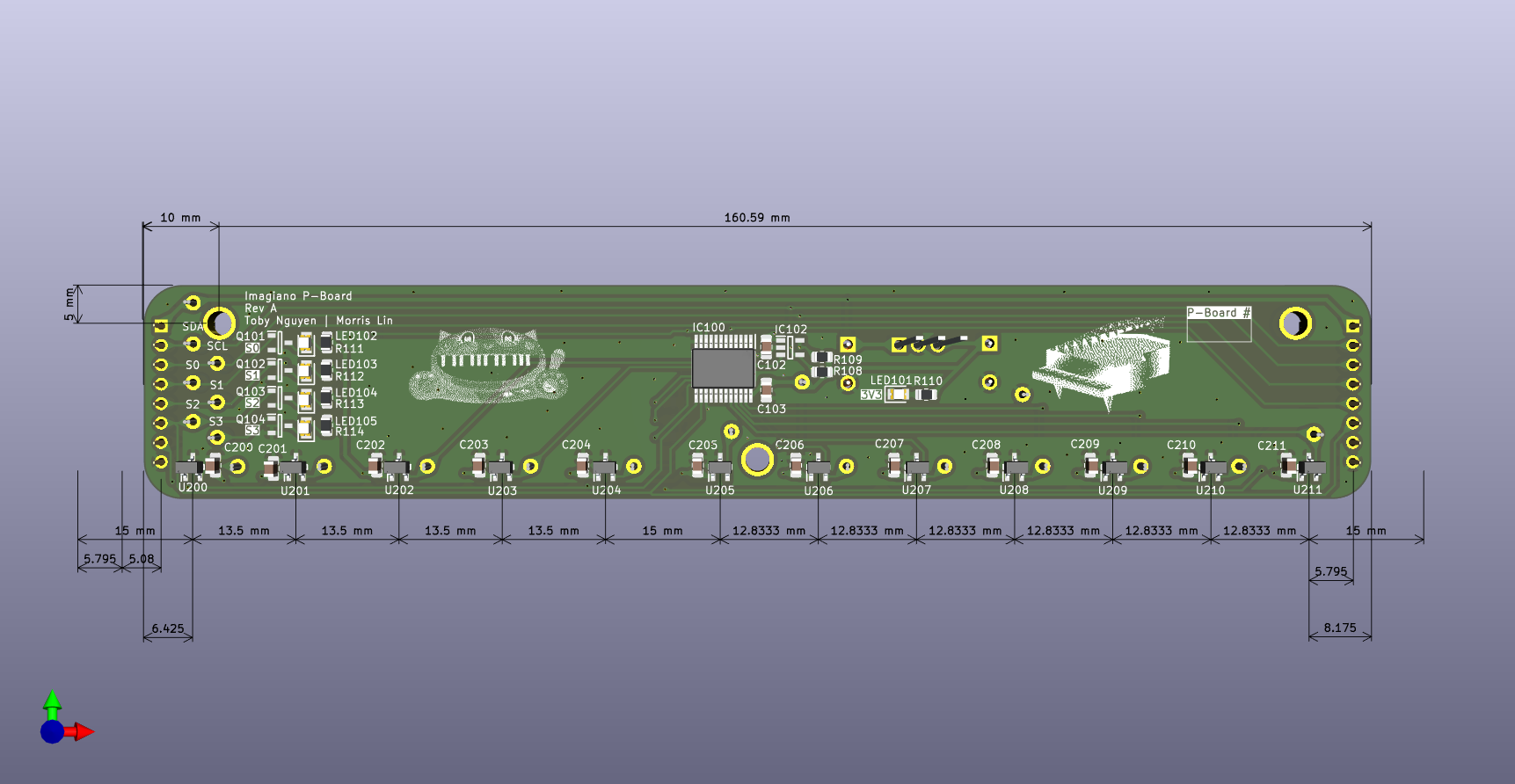 | 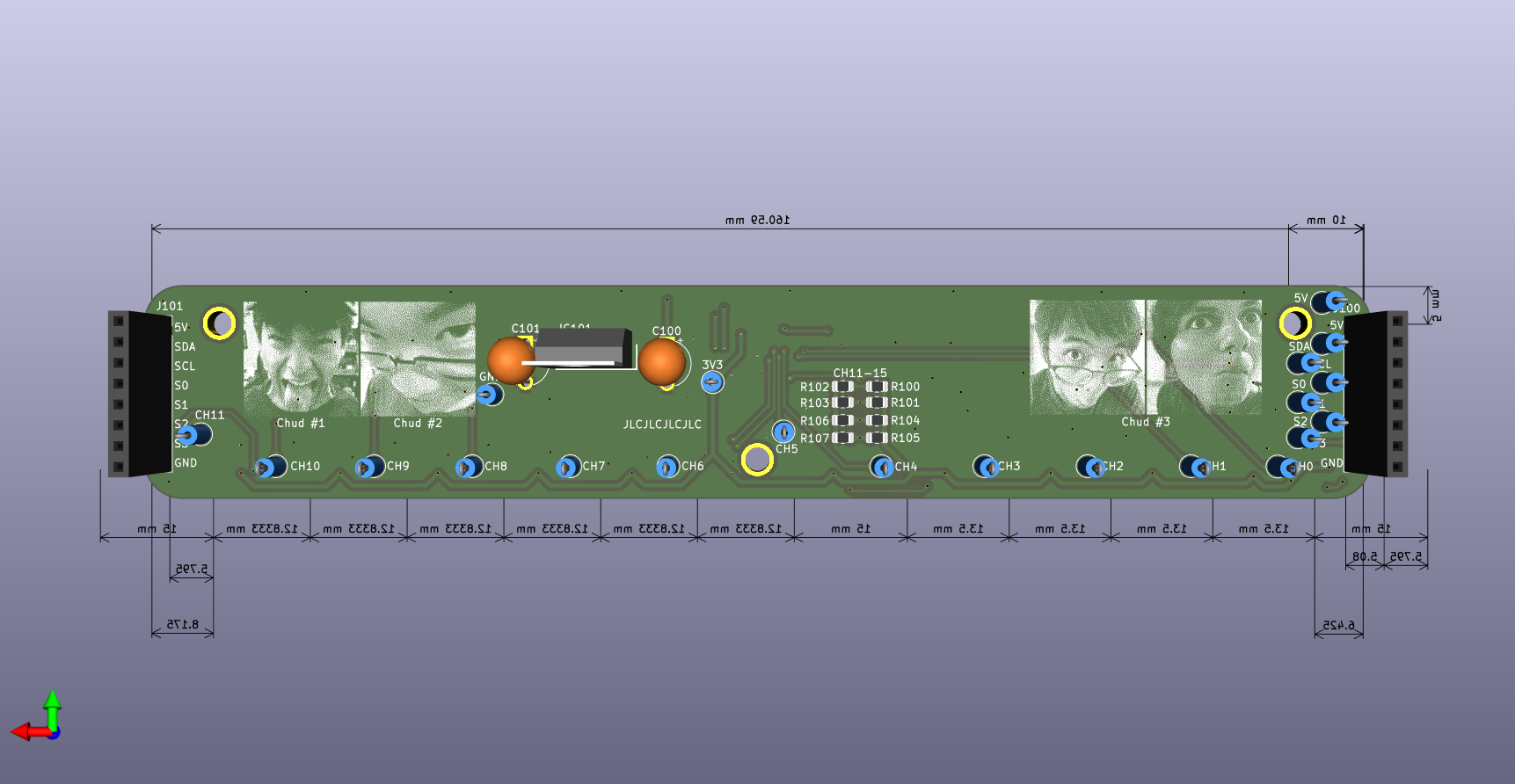 |
| Rev A - Front and back peripheral board | |
TODO: @jeffchang0 cad models pictures?
TODO: @jeffchang0 mechanical design challenges
TODO: talk about mass manufacturing of keys - shoutout "tiw"
Rev A firmware lives in firmware/firmware_v1 and runs on the MSPM0G3507 (LaunchPad fallback or the onboard MCU). Competition rules banned TI SysConfig, so every module we used was brought up by poking registers from the datasheet and TRM. We still leaned on Valvano's class library (inc/) for Clock, LaunchPad GPIO, I2C, timers, and the ST7735 LCD, then wrote our own drivers in lib/ for the piano-specific hardware.
The production main is deliberately tiny: clock + LaunchPad init, DAC + 32 kHz DMA audio, Hall-sensor ADC, then a forever loop that only fills audio buffers. LCD/encoder and LED-strip code exists, but DSP ate so much CPU that we could not keep those loops running in the shipped demo (see Implementation Challenges).
Coding habits that showed up everywhere:
main (key attack/release actions, ping-pong refill bits, encoder "redraw me" flags) instead of doing DSP inside interrupts.int16/int32 with shifts. No floating point on the Cortex-M0+ hot path.BoardConfig.h as a compile-time switch between LaunchPad pinout and the discrete MCU pinout, so we could keep one codebase for both boards.MSPM0 modules we actually used: GPIO (mux select, encoders, heartbeat), I2C1 (peripheral ADCs), TIMA1 (key scan), TIMG0 (audio sample clock / event publisher), DAC12 (speaker), DMA (audio to DAC, and separately LED PWM), TIMG7 + PWM (WS2812B), and GROUP1 GPIO interrupts (encoders).
Each peripheral board has a 16:1 analog mux in front of an I2C ADC (addresses 0x48, 0x49, 0x4A, 0x4C, 0x4D for the five octaves). Only 12 mux channels are wired (one key each); the extra four are unused. Four GPIOB bits (PB20, PB24, PB4, PB3 on the LaunchPad profile) are the mux select lines, which also drive those debug LEDs on the schematic.
TimerA1 fires at 1800 Hz and the ISR samples one key per tick over I2C (I2C_Recv2), then advances the mux. A full 60-key sweep is therefore 30 Hz. That is slow for audio-rate velocity, but it was enough to catch a press vs a rest without blocking the synth.
Because neighboring key magnets had to alternate polarity, even keys treat an ADC rise as "down" and odd keys invert it. Rest is calibrated around 1.7 V (~2110 counts on a 12-bit, 3.3 V full scale). A note attacks only if displacement is past a hysteresis threshold and velocity (delta displacement) is above a noise floor; it releases when the key comes back under the release threshold. The ISR only posts Attack_Key / Release_Key into a mailbox. The synth thread is the one that actually starts/stops oscillators, so we do not re-enter the wavetable from I2C context.
Audio is a 32 kHz, 12-bit two's-complement stream out of DAC12 on PA15. TimerG0 is programmed as a 32 kHz down-counter that publishes a zero-event onto Event Route 1. DMA channel 0 is a circular, repeat-single transfer from a 512-sample ping-pong buffer (256 + 256) into DAC0->DATA0. Half-done and done IRQs set refillPing / refillPong; Synth_Write_Buf() in main fills whichever half just retired.
The voice engine is additive DDS over 60 keys (C2–B6):
freq * 2^32 / 32000, baked into a table with PHASE_INC().PianoLUT). There is also a sine LUT in the tree; piano was what we shipped.Note_Gain[key] (a little extra attenuation on the high notes) times a decaying envelope LUT (625 steps, advanced every 1024 samples). When the envelope runs out, the key is marked inactive.-2048…2047).Polyphony is "all 60 if you mash them," which is exactly why the M0+ had nothing left for the UI.
We wrote a GPIO interrupt driver for two mechanical encoders and a small ST7735 UI on top of Valvano's ST7735 driver.
PB15 CLK, PB16 DT, PB13 switch) walks a four-item instrument menu (Piano / Trumpet / Flute / Oboe) and the pushbutton toggles between the list and a "you selected X" screen.PB19 CLK, PB2 DT) was meant to be volume, clamped 0–20.GROUP1_IRQHandler, then a re-read of the pin. The ISR only sets update_menu / update_screen_type; the commented-out main2 in Main.c is the foreground that would have redrawn.That UI never made it into the competition binary. The synth loop could not share the CPU, so instrument select and volume stayed as unused (but working-in-isolation) drivers.
0 or 1Generic Event 0 to Event Channel 1 every time the counter reached its reload point@jeffchang0 - Mechanical design/fabrication
@MorrisYLin - DAC driver/firmware, DSP firmware, PCB design/validation
@zaarabilal - I2C ADC driver/firmware, LCD/digital encoder drivers/firmware, Mechanical design
@tguyenn - PCB design/validation/assembly, WS2812B LED driver/firmware, Documentation
Due to time and budget restrictions, we weren't able to cleanly implement all of our features. We didn't like that, so we decided to spin a new revision of the main board to add and fix some features.
Some of these features include:
 |  |
| Rev B - Main (Left) and Peripheral (Right) Schematics | |
After verifying the schematic, we moved onto laying out the PCB itself:
 |  |
| Rev B - Front and back main board | |
 |  |
| Rev B - Front and back peripheral board | |
coming soon...™️
| Qty | Value | Footprint | References |
|---|---|---|---|
| 14 | 0u1 | Capacitor_SMD:C_0603_1608Metric | C202, C304, C305, C307, C309, C310, C311, C312, C313, C314, C507, C601, C602, C801 |
| 7 | 10k | Resistor_SMD:R_0603_1608Metric | R303, R307, R308, R601, R602, R603, R604 |
| 7 | 1u | Capacitor_SMD:C_0603_1608Metric | C303, C306, C308, C503, C504, C701, C702 |
| 7 | 470 | Resistor_SMD:R_0603_1608Metric | R202, R301, R302, R401, R402, R403, R404 |
| 4 | 27 | Resistor_SMD:R_0603_1608Metric | R305, R306, R801, R802 |
| 4 | 2x5 Socket Pins | SamacSys_Parts:logic_analyzer_slot_2x5_2.54mm | J402, J503, J601, J701 |
| 4 | MountingHole | SamacSys_Parts:standoff_MH | H101, H102, H103, H104 |
| 4 | NX3020NAK-QR | SamacSys_Parts:SOT95P230X110-3N | Q401, Q402, Q403, Q404 |
| 3 | 10u | Capacitor_SMD:C_0603_1608Metric | C203, C204, C802 |
| 3 | GND | SamacSys_Parts:bettertestpoint2 | TP201, TP701, TP803 |
| 3 | Jumper_2_Small_Bridged | Jumper:SolderJumper-2_P1.3mm_Bridged2Bar_RoundedPad1.0x1.5mm | JP201, JP202, JP301 |
| 3 | Jumper_2_Small_Open | Jumper:SolderJumper-2_P1.3mm_Open_RoundedPad1.0x1.5mm | JP501, JP502, JP503 |
| 2 | 10n | Capacitor_SMD:C_0603_1608Metric | C501, C502 |
| 2 | 15p | Capacitor_SMD:C_0603_1608Metric | C301, C302 |
| 2 | 3u3 | Capacitor_SMD:C_0603_1608Metric | C505, C506 |
| 2 | 47k | Resistor_SMD:R_0603_1608Metric | R503, R504 |
| 2 | 5k1 | Resistor_SMD:R_0603_1608Metric | R203, R204 |
| 2 | 787 | Resistor_SMD:R_0603_1608Metric | R501, R502 |
| 2 | Conn_01x02_Pin | Connector_PinHeader_2.54mm:PinHeader_1x02_P2.54mm_Vertical | J203, J206 |
| 2 | Conn_01x03_Pin | Connector_PinHeader_2.54mm:PinHeader_1x03_P2.54mm_Vertical | J501, J801 |
| 2 | LM321LVIDBVR | SamacSys_Parts:SOT95P280X145-5N | IC501, IC502 |
| 2 | RUN_LED | SamacSys_Parts:LEDC2012X40N | LED301, LED302 |
| 2 | RotaryEncoder_Switch | Rotary_Encoder:RotaryEncoder_Bourns_Vertical_PEC12R-3x17F-Sxxxx | SW601, SW602 |
| 2 | SWD Breakout | Connector_PinHeader_2.54mm:PinHeader_1x02_P2.54mm_Vertical | J202, J205 |
| 1 | 1k | Resistor_SMD:R_0603_1608Metric | R304 |
| 1 | 1k5 | Resistor_SMD:R_0603_1608Metric | R201 |
| 1 | 1x8 Male Pins | Connector_PinSocket_2.54mm:PinSocket_1x08_P2.54mm_Vertical | J401 |
| 1 | 22k1 | Resistor_SMD:R_0603_1608Metric | R206 |
| 1 | 2u2 | Capacitor_SMD:C_0603_1608Metric | C201 |
| 1 | 3V3_PWR | SamacSys_Parts:LEDC2012X40N | LED202 |
| 1 | 51k | Resistor_SMD:R_0603_1608Metric | R205 |
| 1 | 5V_PWR | SamacSys_Parts:LEDC2012X40N | LED201 |
| 1 | 8u2 | Inductor_SMD:L_Abracon_ASPI-4030S | L201 |
| 1 | ABM8-272-T3 | Crystal:Crystal_SMD_3225-4Pin_3.2x2.5mm | Y301 |
| 1 | AP64060TQWU-7 | SamacSys_Parts:SOT95P280X100-6N | IC201 |
| 1 | AT25FF161A-SHN-B | SamacSys_Parts:SOIC127P798X216-8N | IC301 |
| 1 | Barrel_Jack | SamacSys_Parts:373 | J204 |
| 1 | DAC_L | SamacSys_Parts:bettertestpoint2 | TP501 |
| 1 | DAC_R | SamacSys_Parts:bettertestpoint2 | TP502 |
| 1 | DOUT3V3 | SamacSys_Parts:bettertestpoint2 | TP801 |
| 1 | DOUT5V | SamacSys_Parts:bettertestpoint2 | TP802 |
| 1 | HiLetGo_ST7735R | 445L:hiletgo_st7735r | J702 |
| 1 | Jumper_2_Small_Bridged | Jumper:SolderJumper-2_P1.3mm_Open_TrianglePad1.0x1.5mm | JP801 |
| 1 | PCM1780DBQR | SamacSys_Parts:SOP64P600X175-16N | IC503 |
| 1 | R | SamacSys_Parts:bettertestpoint2 | TP504 |
| 1 | RP2040 | SamacSys_Parts:SC091413 | U301 |
| 1 | S | SamacSys_Parts:bettertestpoint2 | TP503 |
| 1 | S0 | SamacSys_Parts:LEDC2012X40N | LED401 |
| 1 | S1 | SamacSys_Parts:LEDC2012X40N | LED402 |
| 1 | S2 | SamacSys_Parts:LEDC2012X40N | LED403 |
| 1 | S3 | SamacSys_Parts:LEDC2012X40N | LED404 |
| 1 | SN74LV1T34DBVR | SamacSys_Parts:SOT95P280X145-5N | IC801 |
| 1 | SWD Breakout | Connector_PinHeader_2.54mm:PinHeader_1x04_P2.54mm_Vertical | J301 |
| 1 | T | SamacSys_Parts:bettertestpoint2 | TP505 |
| 1 | TPD3E001DRLR | SamacSys_Parts:SOTFL50P160X60-5N | IC202 |
| 1 | USBV | SamacSys_Parts:bettertestpoint2 | TP202 |
| 1 | USB_C_Receptacle_USB2.0_16P | Connector_USB:USB_C_Receptacle_GCT_USB4105-xx-A_16P_TopMnt_Horizontal | J201 |
| 1 | VBUS | SamacSys_Parts:bettertestpoint2 | TP203 |
| 1 | XTAL_REF | SamacSys_Parts:bettertestpoint2 | TP301 |
| 1 | trs_audio_jack | 445L:Jack_3.5mm_CUI_SJ1-3523N_Horizontal | J502 |


Andresse2020/NovaDrone-Hardware
Complete electronic system design for a high-performance quadcopter drone, developed entirely from scratch. Includes power distribution, motor control, flight stabilization, sensor integration, and communication…


tomrodinger/servomotor
Open-source NEMA-17 integrated servomotor (motor + closed-loop driver + controller + encoder). RS-485, Python/Arduino libraries, MCP server for AI control. Hardware, firmware and software.


doppelgrau/esp32-f9p-io-board
An IO-PCB (two motor-driver/H-bridge, CAN, RS232, ADS1115, relay, ethernet, ardusimple f9p compatible connector) with an ESP32 for 12V power, three 15V tolerant analog inputs, three 5V tolerant inputs.


123 parts, built around the RP2040, LM321LVIDBVR-TP, AT25FF161A-SHN-B and SN74LV1T34DBVR-TP. The full list of its parts is on this page, with links to each part's symbol and footprint where PCBKit's library has them.
From the tguyenn/digital-synthesizer repository on GitHub, at the commit this page was made from: the board is hardware/main_boardv2/main_boardv2.kicad_pcb and its schematic hardware/main_boardv1/AUDIO_IO.kicad_sch. PCBKit opens the board in the browser, with nothing to install.
Its repository states no licence, so its author keeps all rights: ask tguyenn before reusing the design.