4 layers30.5 × 88.9 mm

 tgtakaoka/retro-bionic6
Modern platform to run retro CPUs
Bionic base is an open-source printed circuit board by tgtakaoka, from the tgtakaoka/retro-bionic repository on GitHub. It is a 2-layer board of 96.5 × 96.5 mm with 41 parts on 107 nets, routed with 789 tracks and 132 vias.
It is built around the TEENSY 4.1, TXS0108EPW and CSL1901UW1. Its parts include 12 capacitors, 7 ICs, 7 connectors, 5 resistors and 1 diode. It belongs with the retro computing and games boards and the NXP (LPC, Kinetis, i.MX RT) boards of this library.



Run real vintage CPUs on a modern Cortex-M7 — with a debugger, assembler and disassembler built in.
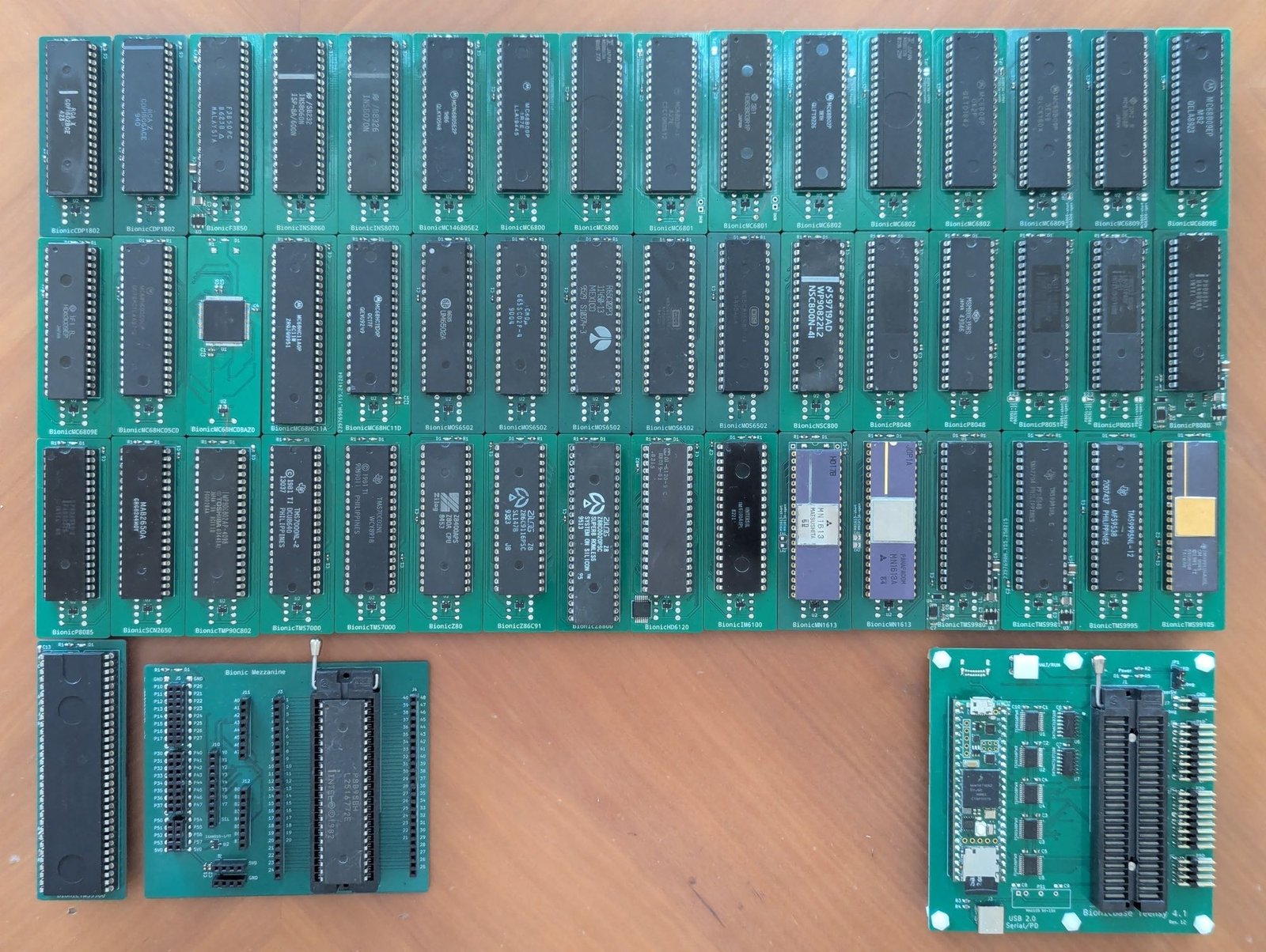
Put a real MC6809, Z80, TMS9900 or CDP1802 into a ZIF socket and single-step it, one bus cycle at a time, from a terminal on your desk.
Bionic runs genuine vintage processors — not emulations of them. A Teensy 4.1 is wired to every pin of the target CPU and drives the whole system around it: the clock, every bus cycle, and the memory and peripherals the chip thinks it is talking to. One firmware image — about 470 kB including every assembler, disassembler and debugger — covers all 50 supported targets, and the board tells the controller which one it is.
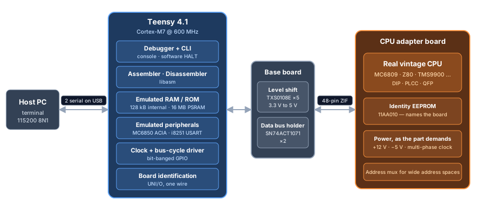
The hardware is two boards:
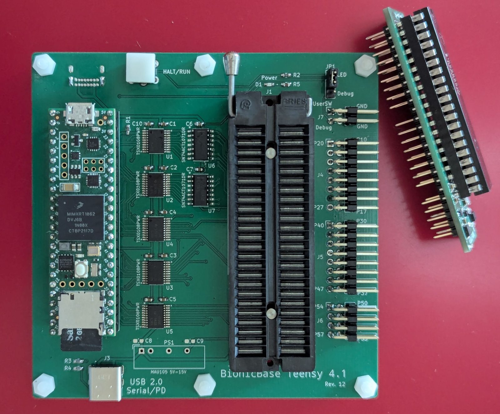
The 48 signals crossing the connector are named P10–P57, and each CPU board maps them to
its own pinout in a small TOML file. See docs/hardware.md.
S).r, =).B, b, g).d, p, m, M), plus a write-protect area on targets that need one (P).U).I).MOS6502, G65SC02, R65C02, W65C02S or
W65C816S depending on which die actually responds.
All 50 targets, grouped by vendor and architecture:
| Vendor | Architecture | Targets |
|---|---|---|
| Motorola | 6800 | MC6800 MB8861, MC6801 HD6301, MC6802 MB8870, MC68HC11A, MC68HC11D |
| 6805 | MC146805E2, MC68HC05C0, MC68HC08AZ0 | |
| 6809 | MC6809 HD6309, MC6809E HD6309E | |
| 68HC12 | MC68HC12B | |
| 68HC16 | MC68HC16Z | |
| MOS Technology | 6502 | MOS6502 G65SC02, R65C02, W65C02S, W65C816S |
| Zilog | Z80 | Z80, Z180, NSC800, KL5C80A12, HD64180S |
| Z280 | Z280 | |
| Z380 | Z380 | |
| Z8000 | Z8001, Z8002 | |
| Z8 | Z86C91, Z88C00 | |
| Intel | MCS-48 | P8048 P8039, MSM80C39 |
| MCS-51 | P8051 | |
| MCS-80/85 | P8080, P8085 | |
| MCS-96 | P8095BH, N8097BH, S80C196K S80C196KB, S80C196KC, S80296SA | |
| Texas Instruments | TMS9900 | TMS9900, TMS9980, TMS9981, TMS9995, TMS99105 TMS99110 |
| TMS7000 | TMS7000 TMS7002 | |
| TMS370 | TMS370Cx5x | |
| TMS320 | TMS320C15 | |
| DEC | PDP-8 | IM6100, HD6120 |
| RCA | COSMAC | CDP1802 CDP1804A |
| Fairchild | F8 | F3850 |
| National | SC/MP II | INS8060 |
| SC/MP III | INS8070 | |
| Signetics | 2650 | SCN2650 |
| Toshiba | TLCS-90 | TMP90C802 |
| Hitachi | H16 | HD641016 |
| Panafacom | MN1610 | MN1613 MN1613A |
Targets in italics are variants the firmware identifies at runtime, by executing instructions that behave differently on each die — not by anything written on the board.
See docs/supported-cpus.md for the full table, including the CPUs still to be supported.
| Path | Contents |
|---|---|
debugger/ | Teensy 4.1 firmware — shared framework plus 25 per-family back ends |
schematics/ | KiCad projects: base, mezzanine, PLCC adapter and 54 CPU adapter boards, with gerbers and PDFs |
pinout/ | Pin-map definitions consumed by dip |
samples/ | Test programs — Mandelbrot, arithmetic suites, serial echo — ported to every CPU |
scripts/ | Bench control, regression, cycle recording and timing scripts, and the PlatformIO compile_commands.json helper |
| Project | Role |
|---|---|
| libasm | The assembler and disassembler engine — 41 architectures, 119 CPU variants, small enough to run on an AVR |
| libcli | The serial command-line front end the debugger is built on |
| dip | Draws the pinout diagrams from the TOML files in pinout/ |
Licensed under the Apache License, Version 2.0.
| Qty | Value | Footprint | References |
|---|---|---|---|
| 12 | 0.1u | Capacitor_SMD:C_0603_1608Metric_Pad1.08x0.95mm_HandSolder | C1, C2, C3, C4, C5, C6, C7, C10, C11, C12, C13, C14 |
| 6 | MountingHole_3.2mm_M3 | MountingHole:MountingHole_3.2mm_M3 | MH1, MH2, MH3, MH4, MH5, MH6 |
| 5 | TXS0108EPW | ti:PW20-M | U1, U2, U3, U4, U5 |
| 2 | 5.1k | Resistor_SMD:R_0603_1608Metric_Pad0.98x0.95mm_HandSolder | R3, R4 |
| 2 | SN74ACT1071DR | ti:D14-M | U6, U7 |
| 2 | USB_C_USB2.0_16P | bionic-base:GCT_USB4085-GF-A_REVB | J2, J3 |
| 1 | 1.6k | Resistor_SMD:R_0603_1608Metric_Pad0.98x0.95mm_HandSolder | R5 |
| 1 | 4.7k | Resistor_SMD:R_0603_1608Metric_Pad0.98x0.95mm_HandSolder | R1 |
| 1 | 560 | Resistor_SMD:R_0603_1608Metric_Pad0.98x0.95mm_HandSolder | R2 |
| 1 | Bionic_ZIF_Socket_48pin | bionic-base:Aries_ZIF_socket_DIP-48-pin | J1 |
| 1 | CSL1901UW1 | rhom:LED_CSL1901UW1_ROM-M | D1 |
| 1 | Debug | Connector_PinHeader_2.54mm:PinHeader_2x02_P2.54mm_Horizontal | J7 |
| 1 | Debug | Connector_PinHeader_2.54mm:PinHeader_1x03_P2.54mm_Vertical | JP1 |
| 1 | P1/P2 | Connector_PinHeader_2.54mm:PinHeader_2x08_P2.54mm_Horizontal | J4 |
| 1 | P3/P4 | Connector_PinHeader_2.54mm:PinHeader_2x08_P2.54mm_Horizontal | J5 |
| 1 | P5 | Connector_PinHeader_2.54mm:PinHeader_2x04_P2.54mm_Horizontal | J6 |
| 1 | Teensy4.1 | bionic-base:Teensy 4.1 | B1 |
| 1 | USR_SW | bionic-base:SW_PUSH_LED_6mm | SW1 |


kwan3217/rocketometer_teensy
Rocketometer -- inertial, pressure, and maybe GPS sensors for measuring a sounding rocket


FPGAwars/icezum
:star2: IceZUM Alhambra: an Arduino-like Open FPGA electronic board

MetalMusings/MyOwnEtherCATDevice
Documentation accompanying the "Make My Own EtherCAT device" video serie on Youtube.

NVIDIA-AI-IOT/my-jetson-nano-baseboard
An open source Jetson Nano baseboard and tools to design your own.

AndreiVladescu/ESP32-Bit-Pirate-Hardware
Carrier breaker-board for the ESP32-S3 Devkit. Works great with the ESP32-Bit-Pirate firmware.
It measures 96.5 × 96.5 mm and has 2 copper layers, 1.6 mm thick.
41 parts, built around the TEENSY 4.1, TXS0108EPW and CSL1901UW1. The full list of its parts is on this page, with links to each part's symbol and footprint where PCBKit's library has them.
From the tgtakaoka/retro-bionic repository on GitHub, at the commit this page was made from: the board is schematics/base/bionic-base.kicad_pcb. PCBKit opens the board in the browser, with nothing to install.
Its repository states no licence, so its author keeps all rights: ask tgtakaoka before reusing the design.