2 layers98 × 27 mm

 terriko/pricklypear
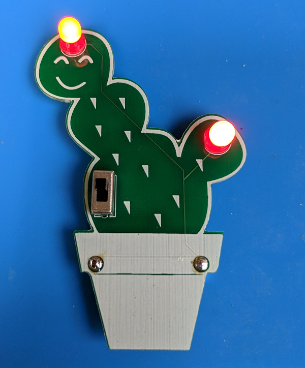
Beginner soldering kit for Albuquerque Mini Maker Faire
Pricklypear is an open-source printed circuit board by terriko, from the terriko/pricklypear repository on GitHub. It is a 2-layer board of 46.4 × 68.8 mm with 5 parts on 4 nets, routed with 19 tracks and 0 vias.
Its parts include 2 diodes and 1 switch.
(c) Terri Oda 2019
License: CC-BY-SA 4.0
When I first moved from Ottawa to Albuquerque, I was constantly fascinated by the cactus growing everywhere, because I'd never seen so many in the wild. I still have a particular fondness for the prickly pear, because it is both pretty and delicious. This soldering kit uses red LEDs to make prickly pear fruit to match up against a green circuit board for the cactus. Sure, real prickly pears don't glow, but given New Mexico's place in nuclear history, it's not too much of a stretch to imagine that they might have in some alternate history.
The parts can be soldered on in any order, but I recommend starting with the battery holder first since the connections are bigger for people who've never soldered before and want a big target to hit on the first try.
Flip the board over so you're looking at the back.
Cover the square near the bottom (above the word "battery") with solder.
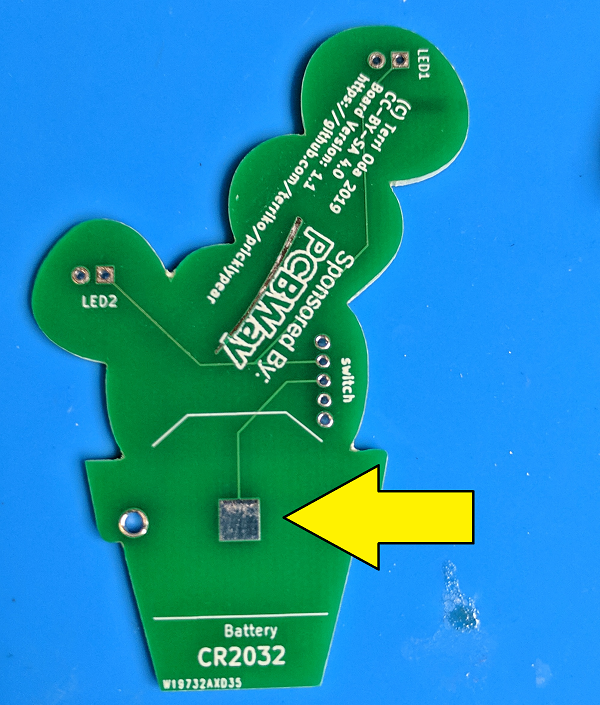
The battery holder is the big metal piece with a + cut into it and a couple of clips. Put it in place over the square. The + sign will be at the top and opening where you insert the battery will be at the bottom. Push the clips through the big holes on either side of the flower pot.
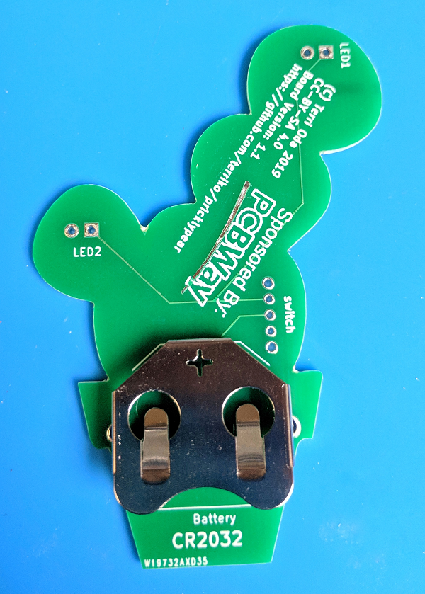
Flip the board over so that you're looking at the front
Solder the two clips in place.
When I made the board, I made 5 holes for this switch, but the outer two are a bit too small, so we won't be using those.
Cut the outermost legs off the switch. You probably want to wear eye protection for this in case bits go flying. Those outer legs are a bit wider than the others. Be careful not to cut the inner three pins!
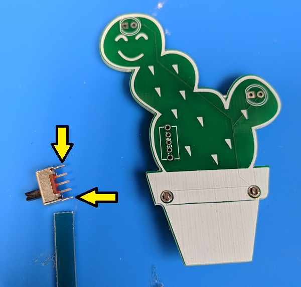
Stick the switch in the space labelled "switch" on the back of the board. The pins should stick out the back and the switch itself should be on the front.
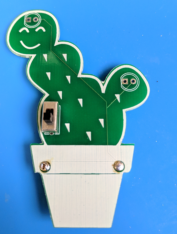
Make sure your three remaining pins are in the inner three slots.
Solder each pin separately. You might notice that the bottom pin isn't connected to anything, so you don't need to solder it, but you probably want to just for stability.
| Qty | Value | Footprint | References |
|---|---|---|---|
| 2 | LED | LEDs:LED_D5.0mm | LED1, LED2 |
| 1 | silkscreens:sillkscreen_pricklypear_pot | ||
| 1 | Battery | Cell_Coin_Holders:Keystone_3003_CR2032_THT | Battery |
| 1 | SW_SPDT | 1825232-1:1825232-1 | SW1 |

joypad-ai/joypad-os
Universal controller firmware for building adapters, dongles, and custom controllers.

OLIMEX/OLINUXINO
OLINUXINO is Open Source / Open Hardware, low cost from EUR 24 Linux Industrial grade Single Board Computer capable to operate -25+85C

jamro/tiny-engineer
A small desktop robot that brings an AI coding assistant to life, physically acting out when it reads files, thinks, writes code, and finishes work.

hackclub/OnBoard
💡 Join 1,000 teenagers and make your first PCB with a $100 grant!


Luos-io/luos_engine
Open-source and real-time orchestrator for cyber-physical-systems, to easily design, test and deploy embedded applications and digital twins.
It measures 46.4 × 68.8 mm and has 2 copper layers, 1.6 mm thick.
5 parts. The full list of its parts is on this page, with links to each part's symbol and footprint where PCBKit's library has them.
From the terriko/pricklypear repository on GitHub, at the commit this page was made from: the board is PricklyPear/PricklyPear.kicad_pcb. PCBKit opens the board in the browser, with nothing to install.
Its repository states no licence, so its author keeps all rights: ask terriko before reusing the design.