2 layers
Nrf bga
github-linguist/linguist
Language Savant. If your repository's language is being reported incorrectly, send us a pull request!
12 parts14kMIT

 tejasvswipe/tars-lite-humanoid
TARS-Lite stationary humanoid prototype with ESP32-S3, Raspberry Pi 5, Arduino, sensors, PCB Gerbers, and printable parts.
TARS Lite DXL Neck is an open-source printed circuit board by tejasvswipe, from the tejasvswipe/tars-lite-humanoid repository on GitHub. It is a 2-layer board of 85 × 55 mm with 12 parts on 10 nets, routed with 66 tracks and 0 vias.
Its parts include 4 resistors, 3 connectors, 2 capacitors, 2 ICs and 1 fuse. It belongs with the ESP32 boards of this library.
Editable board: TARS-Lite-DXL-Neck.kicad_pcb (generated by generate_board.py). Fabrication outputs: gerber/.
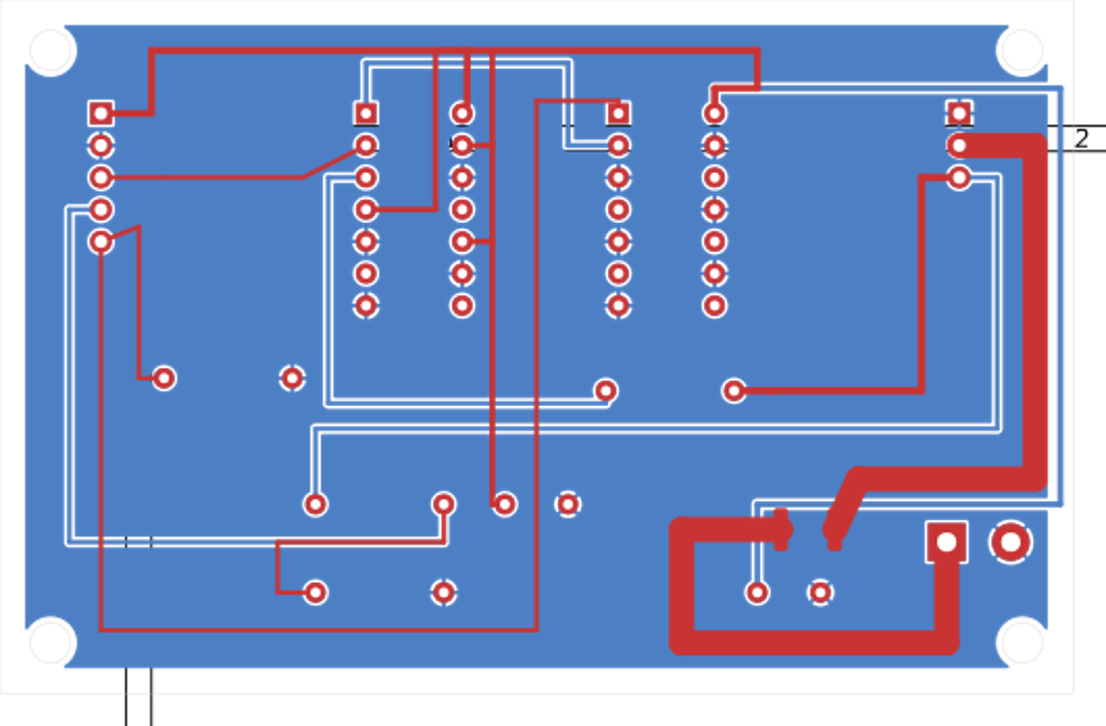
This two-layer board is only the signal-level bridge and fused power branch for one neck-only XL-320. It translates ESP32-S3 3.3 V UART to the actuator's 5 V TTL half-duplex DATA line with a 74HCT125 tri-state driver, a 74HCT14 direction inverter, 220 Ω output series resistor, and 10 kΩ / 20 kΩ receive divider. The 74HCT14 makes the library's active-high transmit direction become the 74HCT125's active-low /OE; a 10 kΩ pull-down keeps the interface in receive/disabled state during reset. Decoupling capacitors are placed at both logic ICs.
It has a separate 2S actuator input, a PTC fuse (2 A hold) and a fused output to one XL-320. Servo power is not sourced from the ESP32 5 V pin. The board is not for the 16-joint leg bus.
| Ref | Pin | Function |
|---|---|---|
| J1 | 1 | +5 V logic from ESP32 board (not servo power) |
| J1 | 2 | GND |
| J1 | 3 | ESP32 UART TX |
| J1 | 4 | ESP32 UART RX (reduced from DXL DATA) |
| J1 | 5 | DXL direction, high while transmitting |
| J2 | 1 | GND |
| J2 | 2 | Fused 2S servo VDD; actuator must see 6.0–8.4 V |
| J2 | 3 | 5 V TTL DXL DATA |
| J3 | 1 | 2S battery +, through board PTC to J2 pin 2 |
| J3 | 2 | GND |
J2 is a 2.54 mm generic header. Use a correctly keyed, strain-relieved adapter to the XL-320's Molex 53253-0370 interface; verify the manufacturer's GND/VDD/DATA order before connecting. Never rely on wire colors alone.
Run /usr/bin/python3 generate_board.py with KiCad 7's pcbnew module, then ./export_gerbers.sh; the export helper runs fill_zones.py in a separate process and saves the filled GND plane before plotting Gerbers. KiCad's connectivity engine reported 0 unconnected items after zone fill. KiCad 7 in this environment has no CLI DRC command, so a full clearance/width DRC must still be run in the KiCad GUI before fabrication. Also inspect component orientation, thermal clearances, drill map, connector keying and fuse datasheet. This is a prototype: no manufacturer DFM review or powered hardware test has been performed.
| Qty | Value | Footprint | References |
|---|---|---|---|
| 2 | 100nF | C_Disc_D5.0mm_W2.5mm_P5.00mm | C1, C2 |
| 2 | 10k | R_Axial_DIN0207_L6.3mm_D2.5mm_P10.16mm_Horizontal | R2, R4 |
| 1 | 20k | R_Axial_DIN0207_L6.3mm_D2.5mm_P10.16mm_Horizontal | R3 |
| 1 | 220R | R_Axial_DIN0207_L6.3mm_D2.5mm_P10.16mm_Horizontal | R1 |
| 1 | 2S AUX POWER IN | TerminalBlock_bornier-2_P5.08mm | J3 |
| 1 | 74HCT125N | DIP-14_W7.62mm_Socket | U1 |
| 1 | 74HCT14N | DIP-14_W7.62mm_Socket | U2 |
| 1 | ESP32: 5V/GND/TX/RX/DIR | PinHeader_1x05_P2.54mm_Vertical | J1 |
| 1 | PTC 2A HOLD | Fuse_1812_4532Metric | F1 |
| 1 | XL-320: GND/VDD/DATA | PinHeader_1x03_P2.54mm_Vertical | J2 |
It measures 85 × 55 mm and has 2 copper layers, 1.6 mm thick.
12 parts. The full list of its parts is on this page, with links to each part's symbol and footprint where PCBKit's library has them.
From the tejasvswipe/tars-lite-humanoid repository on GitHub, at the commit this page was made from: the board is PCB/DXL-Neck/TARS-Lite-DXL-Neck.kicad_pcb. PCBKit opens the board in the browser, with nothing to install.
Its repository states no licence, so its author keeps all rights: ask tejasvswipe before reusing the design.
github-linguist/linguist
Language Savant. If your repository's language is being reported incorrectly, send us a pull request!


google/mozc-devices
Circuit diagrams and firmware source code for Gboard DIY keyboards


hackclub/OnBoard
💡 Join 1,000 teenagers and make your first PCB with a $100 grant!

VoronDesign/Voron-Tap
Tap is a nozzle-based z-probe for the V2 and Trident printer designs. The entire toolhead moves to trigger an optical switch. Tap offers many advantages:

stacksmashing/pico-tpmsniffer
A simple, very experimental TPM sniffer for LPC bus