
2 layers148 × 84.5 mm
Panel daisy
ohmtech-rdi/eurorack-blocks
Software to Hardware Prototyping for Eurorack using C++, Max/Gen~ or Faust
259 parts410

 tdarlic/liteplacer_vacuum_sensor
Vacuum sensor for heavily modified Liteplacer machine
Liteplacer vacuum sensor is an open-source printed circuit board by tdarlic, from the tdarlic/liteplacer_vacuum_sensor repository on GitHub. It is a 2-layer board of 56 × 20 mm with 19 parts on 12 nets, routed with 45 tracks and 22 vias.
It is built around the MCP6001U-I/OT and MPXV6115VC6U. Its parts include 5 capacitors, 3 resistors, 2 ICs and 1 connector. It belongs with the sensors and measurement boards of this library.


Small analog vacuum-sensor board for a pick-and-place machine (LitePlacer-style, Smoothieboard v1.1 + OpenPnP 2.6). It measures the vacuum at the nozzle so OpenPnP can check that a part was picked (Part On) and released (Part Off).
M105Full design notes, calculations, bring-up, Smoothieware and OpenPnP configuration are in
vacuum-sensor.md.
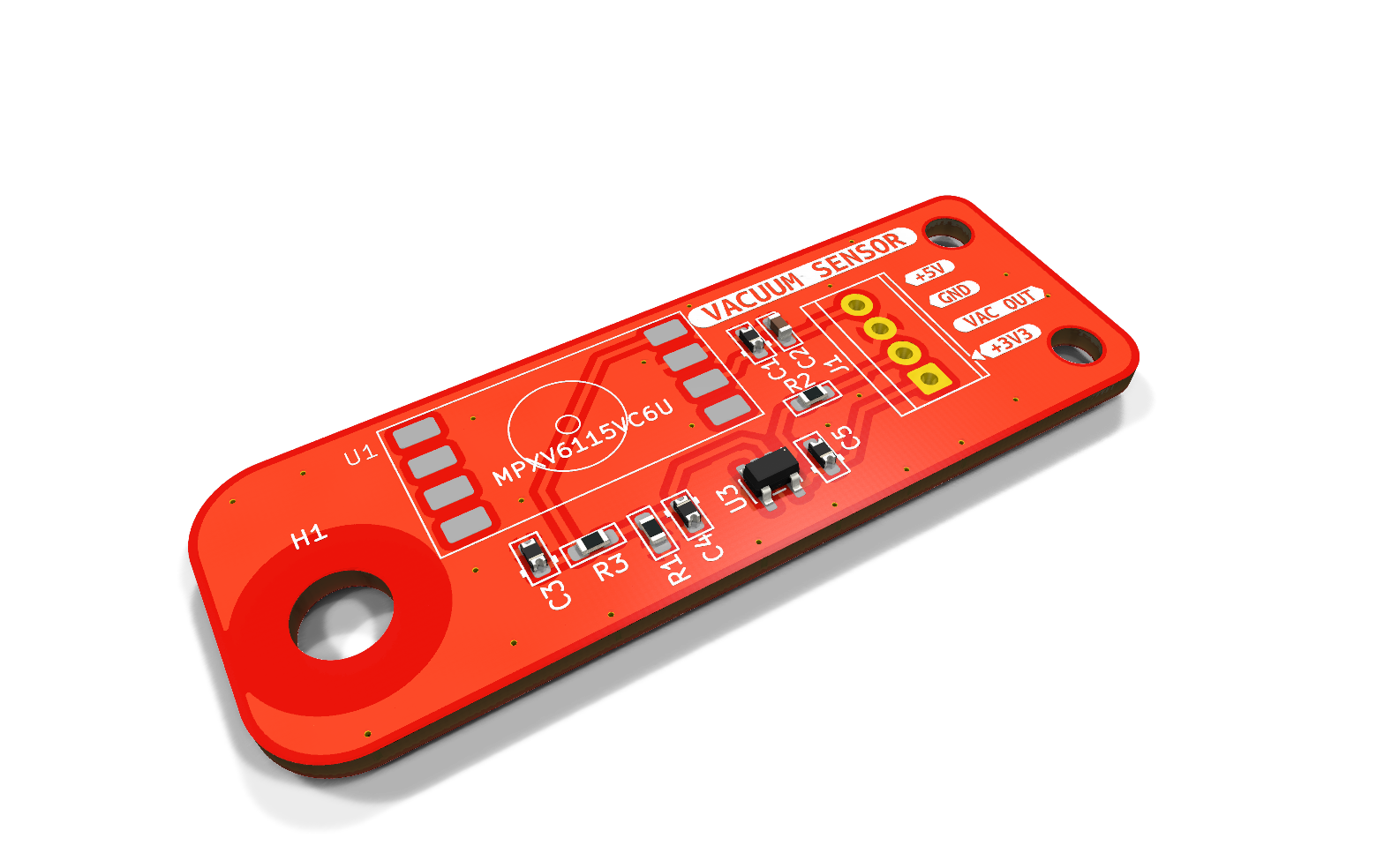
| Top | Bottom |
|---|---|
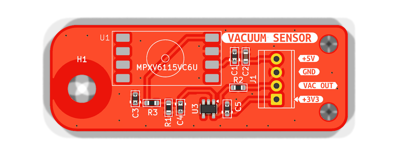 | 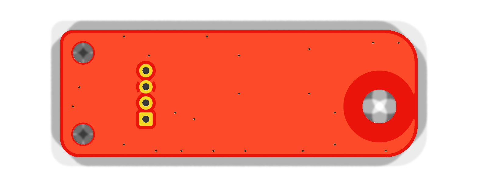 |
The 3D renders show only the footprint pads for U1 (sensor) and J1 (terminal block), because those parts have no 3D model in the project.
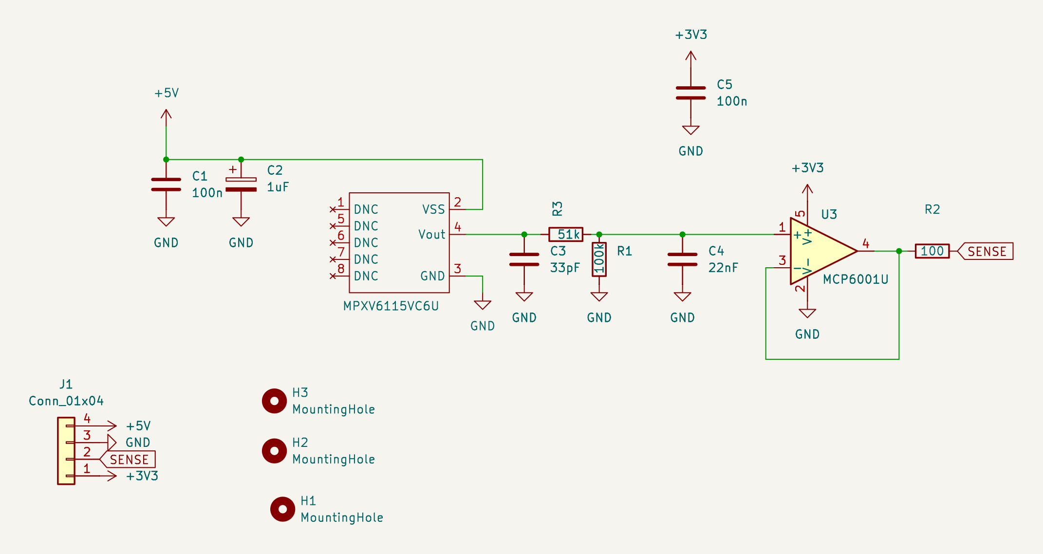
Also available as SVG and PDF.
MPXV6115V (5 V)  ──  R3 51k / R1 100k divider (×0.662)  ──  MCP6001U follower (3.3 V)  ──  R2 100 Ω  ──  Smoothie P0.23
4.6 V at atmosphere      + C3 33 pF, C4 22 nF (~210 Hz low-pass)                                          (T0 thermistor input)
0.2 V at full vacuumLower reading = more vacuum.
| Pin | Signal | Smoothieboard v1.1 |
|---|---|---|
| 1 (square) | +3V3 | 3.3 V pin of the VBB / 3.3V / GND connector |
| 2 | VAC OUT (SENSE) | P0.23 – T0 thermistor input, signal pin |
| 3 | GND | GND on the serial debug header |
| 4 | +5V | 5 V on the serial debug header |
⚠ The Smoothie's VBB / 3.3V / GND connector also carries VBB (12–24 V motor supply). A wire on the wrong pin destroys the op-amp and probably the LPC1769. Check with a meter before powering up.
| Ref | Value | Package | Note |
|---|---|---|---|
| U1 | MPXV6115VC6U | SOP-8 (side port) | Pins 1, 5–8 must stay unconnected |
| U3 | MCP6001UT-I/OT | SOT-23-5 | Must be the U pinout (1 = VIN+, 4 = VOUT) |
| R3 | 51 kΩ 1 % | 0603 | Divider top |
| R1 | 100 kΩ 1 % | 0603 | Divider bottom |
| R2 | 100 Ω | 0603 | Output isolation resistor |
| C1 | 100 nF | 0603 | Sensor supply decoupling |
| C2 | 1 µF | 0603 | Sensor supply bulk |
| C3 | 33 pF | 0603 | Sensor output filter |
| C4 | 22 nF | 0603 | Low-pass with the divider (fc ≈ 210 Hz); 47 nF for ≈ 100 Hz |
| C5 | 100 nF | 0603 | Op-amp bypass |
| J1 | 4-pin terminal block, 2.54 mm | TE 282834-4 |
Reference designators here follow the KiCad design.
vacuum-sensor.mduses the numbering from the original hand-wired prototype (there R1 = 51k, R2 = 100k, R3 = 100 Ω).
Sensor supply 5.0 V, reading from Smoothieware ad8495 channel (reading = V / 0.005):
| Vacuum | Sensor out | Op-amp out | At Smoothie pin* | V: reading |
|---|---|---|---|---|
| 0 kPa (atmosphere) | 4.60 V | 3.05 V | 3.05 V | ≈ 610 (measured 614) |
| −40 kPa | 3.07 V | 2.03 V | 2.06 V | ≈ 410 |
| −60 kPa | 2.30 V | 1.53 V | 1.56 V | ≈ 310 |
| −80 kPa | 1.54 V | 1.02 V | 1.07 V | ≈ 215 |
| −115 kPa (full) | 0.20 V | 0.13 V | 0.20 V | ≈ 40 |
* The Smoothie's 4.7 kΩ pull-up and R2 add a small linear offset; OpenPnP only compares readings, so it doesn't matter.
Smoothieware config:
temperature_control.vacuum.enable          true
temperature_control.vacuum.sensor          ad8495
temperature_control.vacuum.ad8495_pin      0.23
temperature_control.vacuum.ad8495_offset   0
temperature_control.vacuum.designator      V
temperature_control.vacuum.heater_pin      nc
temperature_control.vacuum.max_temp        1000      # must be above 660, or Smoothie HALTs
OpenPnP actuator (Double): read command M105, read regex .*V:(?<Value>-?\d+\.?\d*).*,
set as the nozzle's Vacuum Sense Actuator.
The air line needs a restriction between the constantly running pump and the nozzle/sensor tee, otherwise the
reading is the same with the tip open or blocked. See §8b of vacuum-sensor.md for measured
values and starting part-detection thresholds.
| File | Content |
|---|---|
liteplacer_vacuum_sensor.kicad_pro/.kicad_sch/.kicad_pcb | KiCad project (KiCad 10) |
vacuum-sensor.md | Full design and integration notes |
images/ | Renders and schematic exports |
1735222.pdf | MPXV6115V datasheet (Freescale) |
DS_mpxv6115v6.pdf | MPXV6115V6 datasheet (ST, second source) |
kicad-cli pcb render -o images/pcb-top.png    --side top    --width 1600 --height 640 --quality high --zoom 1.9 liteplacer_vacuum_sensor.kicad_pcb
kicad-cli pcb render -o images/pcb-bottom.png --side bottom --width 1600 --height 640 --quality high --zoom 1.9 liteplacer_vacuum_sensor.kicad_pcb
kicad-cli pcb render -o images/pcb-iso.png    --side top --rotate '-40,0,30' --perspective --width 1600 --height 1000 --quality high --zoom 1.1 liteplacer_vacuum_sensor.kicad_pcb
kicad-cli sch export svg -o images --exclude-drawing-sheet liteplacer_vacuum_sensor.kicad_sch && mv images/liteplacer_vacuum_sensor.svg images/schematic.svg
kicad-cli sch export pdf -o images/schematic.pdf liteplacer_vacuum_sensor.kicad_sch| Qty | Value | Footprint | References |
|---|---|---|---|
| 2 | 100n | PCM_Diode_SMD_Handsoldering_AKL:D_0603_1608Metric_Castellated | C1, C5 |
| 2 | MountingHole | MountingHole:MountingHole_3.2mm_M3 | H2, H3 |
| 1 | 100 | PCM_Resistor_SMD_AKL:R_0603_1608Metric_Pad1.05x0.95mm_HandSolder | R2 |
| 1 | 100k | PCM_Resistor_SMD_AKL:R_0603_1608Metric_Pad1.05x0.95mm_HandSolder | R1 |
| 1 | 1uF | PCM_Capacitor_SMD_AKL:C_0603_1608Metric_Pad1.08x0.95mm_HandSolder | C2 |
| 1 | 22nF | PCM_Diode_SMD_Handsoldering_AKL:D_0603_1608Metric | C4 |
| 1 | 33pF | PCM_Diode_SMD_Handsoldering_AKL:D_0603_1608Metric | C3 |
| 1 | 51k | PCM_Resistor_SMD_AKL:R_0603_1608Metric_Pad1.05x0.95mm_HandSolder | R3 |
| 1 | Conn_01x04 | TerminalBlock_TE-Connectivity:TerminalBlock_TE_282834-4_1x04_P2.54mm_Horizontal | J1 |
| 1 | G*** | kibuzzard-6ABBD2E9 | kibuzzard-6ABBD2E9 |
| 1 | G*** | kibuzzard-6ABBD2B0 | kibuzzard-6ABBD2B0 |
| 1 | G*** | kibuzzard-6ABBD2C7 | kibuzzard-6ABBD2C7 |
| 1 | G*** | kibuzzard-6ABBD306 | kibuzzard-6ABBD306 |
| 1 | G*** | kibuzzard-6ABBD49C | kibuzzard-6ABBD49C |
| 1 | MCP6001U | Package_TO_SOT_SMD:SOT-23-5 | U3 |
| 1 | MPXV6115VC6U | Special_Local:MPXV6115VC6U | U1 |
| 1 | MountingHole | MountingHole:MountingHole_5.3mm_M5_DIN965 | H1 |
ohmtech-rdi/eurorack-blocks
Software to Hardware Prototyping for Eurorack using C++, Max/Gen~ or Faust


MarkSherstan/Drone
Mechanical, electrical, and software package for a custom quadcopter drone.


landjas09/SPECTRA-MX-1-
A four-layer mixed-signal PCB designed in KiCad for analog signal acquisition and generation, targeting the 20 Hz–20 kHz range.


echolevel/open-amiga-sampler
Open source schematics, parts lists and documentation for building generic mono Amiga sampler cartridges

It measures 56 × 20 mm and has 2 copper layers, 1.6 mm thick.
19 parts, built around the MCP6001U-I/OT and MPXV6115VC6U. The full list of its parts is on this page, with links to each part's symbol and footprint where PCBKit's library has them.
From the tdarlic/liteplacer_vacuum_sensor repository on GitHub, at the commit this page was made from: the board is liteplacer_vacuum_sensor.kicad_pcb and its schematic liteplacer_vacuum_sensor.kicad_sch. PCBKit opens the board in the browser, with nothing to install.
Its repository states no licence, so its author keeps all rights: ask tdarlic before reusing the design.