
2 layers16 × 16 mm
Korry pcb v2
aryanma11ick/Home_Cockpit_Project
A custom-built modular home cockpit system for flight simulation, focused on replicating real aircraft controls using PCB design, CAD modeling, and embedded systems.
6 parts1

 tdarlic/tigsich
TIGSICH – finger remote for IPOTools SuperTIG 200Di TIG machine
Tigsich is an open-source printed circuit board by tdarlic, from the tdarlic/tigsich repository on GitHub. It is a 2-layer board of 70.3 × 11.5 mm with 5 parts on 7 nets, routed with 31 tracks and 0 vias.
It is built around the PTA2043-2015CPB503 and TL2230EEF140. Its parts include 1 connector and 1 switch.
A passive, torch-mounted current control that replaces the IPOTools FT-47K-CL8 foot pedal. A finger bar under the index finger does both jobs. Sliding it moves a slide pot, which sets the welding current. Pressing it clicks a push-on / push-off switch underneath, which starts or stops the arc at any current setting. The concept is the same as the 6061 Slide Lever.
Status: design rev 4, not yet prototyped. All board parts are in stock at Mouser (see section 7). The socket voltages on the machine have not been measured yet. See Open items.
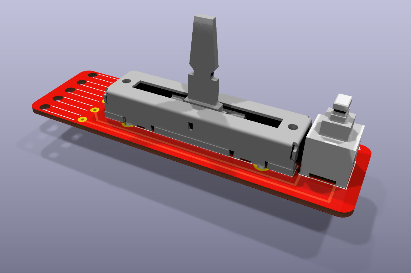
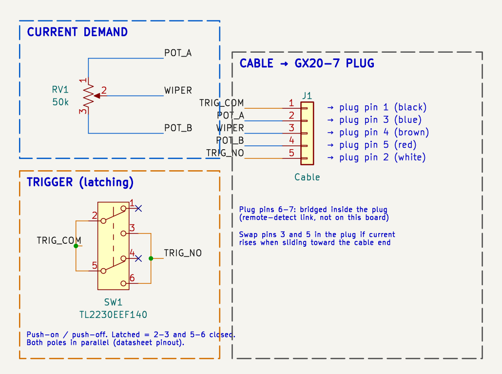
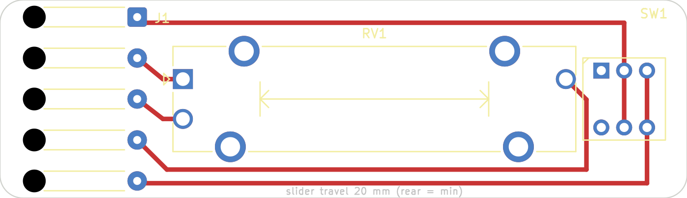
| Schematic | PCB (top) | 3D top view |
|---|---|---|
 |  | 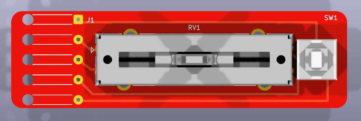 |
The machine has a GX20 7-pin remote socket. The pinout is the same one used by AHP/PrimeWeld pedals
(configuration.jpeg). It was confirmed by measuring the user's own FT-47K-CL8 pedal:
| Plug pin | Wire colour (diagram) | Function | Measured on FT-47K-CL8 |
|---|---|---|---|
| 1 | black | trigger contact | open → short when pedal pressed |
| 2 | white | trigger contact | 〃 |
| 3 | blue | pot end A | 3–4 and 4–5 swing 0.5 kΩ … 50 kΩ in opposite directions |
| 4 | brown | pot wiper | |
| 5 | red | pot end B | |
| 6–7 | – | remote-detect link | 0 Ω (bridged inside the plug) |
Decisions based on this:
There is no power pin on this plug. The only voltages present are the pot reference (across 3–5) and the trigger pull-up (across 1–2). Machines of this type typically put 5–15 V there, so the design assumes ≈12 V. Because the design is passive, the voltage only has to stay within the parts' ratings:
| Part | Rating | Margin at 12 V |
|---|---|---|
| PTA2043 (20 mm, linear) | 200 V DC, 0.1 W | 12 V across 50 kΩ = 2.9 mW |
| TL2230 | 30 V DC, 100 mA | fine for a signal-level input |
| Option | Outcome |
|---|---|
| Hall sensor + MCU + digital pot | Rejected. Needs power, and the plug has no supply pin. It would have to steal current from a 47 kΩ pot reference (≈0.2 mA) or use a battery. It also needs a high-voltage digital pot plus HF-start hardening. |
| Rev 1: finger lever (bell-crank) driving a slide pot | Rejected on size. A 35° swing needs a 25 mm drive arm to move the slider 15 mm, which put the lever top about 50 mm above the PCB. The board was 22.5 mm wide. |
| Rev 2: thumb slider + C&K PVA1 EE H4 latching button | Rejected on height. The PVA1 is 15 mm tall above the PCB, which set a 2 mm lid and a total height of about 20 mm. The target is under 15 mm. |
| Rev 3: index-finger bar + 15 mm PTA1543 | Replaced on sourcing. No 50 kΩ PTA1543 variant is stocked at Mouser (or LCSC). |
| Rev 4: index-finger bar on the lug of a 20 mm PTA2043, pressing an E-Switch TL2230 latching button (chosen) | Passive. One bar for both current and arc on/off. ≈14.7 mm maximum height (bar top), 60.1 × 17.4 × 1.0 mm board. Every part in stock at Mouser. |
How it's used:
The machine stays in 2T mode. The trade-off is that nothing stops the arc if you drop the torch: that takes a
deliberate press. The same footprint takes the momentary TL2230OAF140 (hold to weld) if that's preferred.
| Ref | Part | Why |
|---|---|---|
| RV1 | Bourns PTA2043-2015CPB503: 20 mm travel, 50 kΩ linear, single gang, PC pins, no centre detent, 15 mm metal (CP) lever | The 15 mm PTA1543 we wanted isn't stocked at Mouser; this one is (≈ 900 pcs). Same series, pinout and ratings, with a 35 mm body (+5 mm board length). 20 mm travel ≈ 10 A/mm on a 200 A machine, which is finer control than 15 mm. No detent: the second digit 0 in -2015… (a 2 there means a centre detent). The metal lever lug is cut down to ≈ 13 mm above the PCB bottom and drilled for the finger-bar hinge pin (A); metal drills more cleanly than the insulated lever. |
| SW1 | E-Switch TL2230EEF140: DPDT, latching (EE), 140 gf, 7 × 7 mm, THT | The lowest latching switch with a proper datasheet that I found. Plunger top 12.5 mm above the PCB (11.5 mm latched). 1.0 mm to latch, 1.8 mm full travel. The datasheet shows the pinout and contact states explicitly. |
| J1 | Solder pads with strain-relief holes, 3.6 mm pitch (tigsich:SolderWire-0.15sqmm_1x05_P3.6mm…_Relief, a copy of KiCad's 4 mm version) | No connector to shake loose on a torch. The wire passes up through a 2 mm hole before reaching its pad, so it's held in place. |
| Cable | 5 × 0.14 mm² flexible (insulation OD ≤ 1.5 mm), ~4 m, GX20-7 female plug | Same length as the original pedal (4.3 m). |
Switches I compared (button heights above the PCB bottom, for a 1.6 mm PCB; subtract 0.6 mm for the 1.0 mm board):
| Switch | Size (mm) | Button top: unlatched / latched | Verdict |
|---|---|---|---|
| C&K PVA1 EE H4 | 9.8 × 9.2 | 16.6 / 15.1 | Too tall (rev 2) |
| E-Switch TL2230EEF140 | 7 × 7 | 14.1 / 13.1 | Chosen |
| Alps SPEF110100 | 12.2 wide, 9 deep | ≈ 14.6 unlatched | Wider, only 14.5 V DC rated |
| Generic 5.8 mm "self-lock" switches | 5.8 × 5.8 | similar | No trustworthy datasheet |
Switch wiring: both poles are in parallel. The TL2230 datasheet shows rest = 1–2 and 4–5 closed, and pushed / latched = 2–3 and 5–6 closed. So 2 + 5 → TRIG_COM and 3 + 6 → TRIG_NO, and the rest contacts 1 and 4 are left unconnected. The two contacts in parallel give redundancy for a low-level signal.
Switch life is the weak point. The TL2230 is rated for 10,000 electrical cycles, about 5,000 welds (on + off). That's fine for hobby use, and it's a cheap THT part that's easy to replace.
Pot life: the PTA is rated at 15,000 slide cycles. With a set-and-leave slider (rather than a pedal that moves on every weld) that lasts a long time. A conductive-plastic slide pot of the same footprint is the upgrade path.
No filtering or ESD parts on the board. The original pedal is a bare pot and switch, and the machine's input circuitry was designed for that. If HF-start interference shows up, the first fix is a shielded cable with the shield grounded at the machine end.
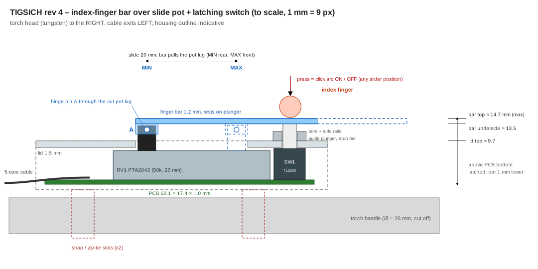
docs/mechanism.svg)The finger bar:
Lid features around the switch:
All heights are measured from the PCB bottom, using nominal datasheet values, with a 1.0 mm PCB:
| Item | Height |
|---|---|
| PCB | 1.0 mm |
| Pot body top | 7.5 mm |
| TL2230 body top | 8.0 mm |
| Lid (1.5 mm), resting just above the switch body | 8.2 → 9.7 mm |
| Hinge pin A (in the cut lug) | ≈ 12.2 mm |
| Plunger top = bar underside (unlatched / latched) | 13.5 / 12.5 mm |
| Finger bar top (1.2 mm bar), highest point | ≈ 14.7 mm (13.7 mm latched) |
The height target (< 15 mm) is met. A 1.6 mm PCB would add 0.6 mm (≈ 15.3 mm). A 1.5 mm aluminium bar would add another 0.3 mm. Add the housing floor under the PCB (≈ 1–1.5 mm) to get the total thickness on the torch.
Other housing notes:
| J1 pad | Silk | Net | Plug pin | Diagram colour |
|---|---|---|---|---|
| 1 | P1 | TRIG_COM | 1 | black |
| 2 | P3 | POT_A | 3 | blue |
| 3 | P4 | WIPER | 4 | brown |
| 4 | P5 | POT_B | 5 | red |
| 5 | P2 | TRIG_NO | 2 | white |
Potentiometer_Bourns_PTA2043_Single_Slide puts pin 3 at
33.0 mm from pin 1, but the datasheet (dimension E) and Bourns' STEP model both give 33.5 mm. With Ø1.2 mm holes
and 0.8 mm pins, the library version would not let the pot seat. The project copy
(tigsich.pretty/Potentiometer_Bourns_PTA2043_Single_Slide_E33.5) keeps pins 1/2 where they were, moves pin 3 to
33.5 mm, and shifts the four mounting tabs and body outline by +0.25 mm, so everything is centred at 16.75 mm as on the part.tigsich.pretty/SW_E-Switch_TL2230), because KiCad's library doesn't have one.
It was made from the datasheet PCB layout (component side): 2 rows of 3 × Ø0.8 mm holes, 2 mm pitch, rows 5 mm apart,
pin 1 square. The pad numbers match the Switch:SW_Push_DPDT symbol: B = common 2/5, A = rest 1/4, C = pushed 3/6.tigsich.3dshapes/TL2230xxFxxx.stp, inch units). It is set in the footprint
with a 90° rotation (the vendor model has its pin rows along Y) and a +0.75 mm Z offset (model origin is 0.75 mm above
the seating plane). With these, the pins sit centred in the pads and the plunger top is 12.5 mm above the PCB, as in
the datasheet.tigsich.3dshapes/PTA2043-2015DPB103.stp, mm). Its "up" is −Z and pin 2 is at +Y,
so the footprint flips it 180° about X and offsets it by (−0.85, +2.9, 0) mm. That centres the body on the tabs and puts
all pins and tabs in their holes, with the body seated on the board.…DPB103). We order
CP (PTA2043-2015CPB503). The body, pins and slot are identical, but the lever shape differs (the DP lever in
the model reaches ≈ 20.7 mm above the PCB top). Take the lever dimensions for the case from the datasheet's CP lever drawing,
or measure the real part. The lever is cut down anyway.Verification:
| Path | Content |
|---|---|
tigsich.kicad_pro/.kicad_sch/.kicad_pcb | KiCad project |
tigsich.pretty/ | Project footprints: TL2230, corrected PTA2043 (E = 33.5 mm), 3.6 mm pitch cable pads |
tigsich.3dshapes/ | Vendor STEP models: TL2230 (E-Switch), PTA2043 DP-lever variant (Bourns) |
docs/mechanism.svg | Scaled side view: finger bar, hinge, switch, heights |
docs/schematic.pdf / .png | Schematic exports |
docs/render.png, docs/render_top.png, docs/pcb_layout.png | 3D renders (KiCad, vendor STEP models) and copper/silk plot |
configuration.jpeg | 7-pin plug pinout reference |
Stock and prices were checked on 2026-09-23 through the pcbparts MCP (Mouser API, USD).
| Ref | Qty / unit | Spare | Manufacturer part | Mouser no. | Stock | Price (USD) |
|---|---|---|---|---|---|---|
| RV1 | 1 | +2 (lug cutting / drilling trials) | Bourns PTA2043-2015CPB503 | 652-PTA20432015CPB50 | 893 | 1.76 (1+), 1.35 (10+) |
| SW1 | 1 | +9 (wear part, 10k cycles) | E-Switch TL2230EEF140 | 612-TL2230EEF140 | 4,614 | 0.85 (1+), 0.75 (10+) |
| – | 1 reel (5,000) | – | YAGEO RC0603FR-07100KL (100 kΩ 1 % 0603, general stock, not used on this board) | 603-RC0603FR-07100KL | 5.1 M | 0.003 (5,000+) |
The Mouser order comes to ≈ $30, under Mouser's EU free-shipping threshold (≈ €50). Mouser ships to the EU with duty and VAT included, so there's no customs agent. Add other stock parts to reach the threshold.
Not at Mouser (buy elsewhere):
| Item | Suggested source |
|---|---|
| Cable 5 × 0.14 mm², ~4.3 m | LAPP UNITRONIC LiYY 5x0.14 (LAPP 0028205) at TME, or any flexible 5-core; shielded LiYCY 5x0.14 (0034305) if HF-start noise appears |
| GX20 7-pin female cable plug | Generic "aviation" connector (local shop, Amazon.de/eBay), or reuse the FT-47K-CL8 pedal's plug; bridge pins 6-7 inside |
| PCB 60.1 × 17.4 × 1.0 mm, 2 layers | Any EU/CN PCB fab (thickness 1.0 mm must be specified) |
| Hinge pin Ø 1 mm, M2 screws ×2 (lid → pot), finger bar 1.2 mm | Hardware store / printed or machined parts |
| Qty | Value | Footprint | References |
|---|---|---|---|
| 2 | MountingHole | MountingHole:MountingHole_3.2mm_M3 | H1, H2 |
| 1 | 50k | tigsich:Potentiometer_Bourns_PTA2043_Single_Slide_E33.5 | RV1 |
| 1 | Cable | tigsich:SolderWire-0.15sqmm_1x05_P3.6mm_D0.5mm_OD1.5mm_Relief | J1 |
| 1 | TL2230EEF140 | tigsich:SW_E-Switch_TL2230 | SW1 |
It measures 70.3 × 11.5 mm and has 2 copper layers, 1.6 mm thick.
5 parts, built around the PTA2043-2015CPB503 and TL2230EEF140. The full list of its parts is on this page, with links to each part's symbol and footprint where PCBKit's library has them.
From the tdarlic/tigsich repository on GitHub, at the commit this page was made from: the board is tigsich.kicad_pcb and its schematic tigsich.kicad_sch. PCBKit opens the board in the browser, with nothing to install.
Its repository states no licence, so its author keeps all rights: ask tdarlic before reusing the design.
aryanma11ick/Home_Cockpit_Project
A custom-built modular home cockpit system for flight simulation, focused on replicating real aircraft controls using PCB design, CAD modeling, and embedded systems.

heyitsarthur/Capstone-Project-Smart-glasses-for-the-visually-impaired
The system operates on a distributed architecture split between a head-mounted sensor array and a chest-mounted compute module. Main Computing Unit: Raspberry Pi Compute Module 4 (CM4) running on a custom PCB.


joypad-ai/joypad-os
Universal controller firmware for building adapters, dongles, and custom controllers.

OLIMEX/OLINUXINO
OLINUXINO is Open Source / Open Hardware, low cost from EUR 24 Linux Industrial grade Single Board Computer capable to operate -25+85C

jamro/tiny-engineer
A small desktop robot that brings an AI coding assistant to life, physically acting out when it reads files, thinks, writes code, and finishes work.

hackclub/OnBoard
💡 Join 1,000 teenagers and make your first PCB with a $100 grant!
