2 layers85 × 109 mm

 tclarke/neo8_adapter2
uBlox NEO-8Q and NEO-M8 breakout board
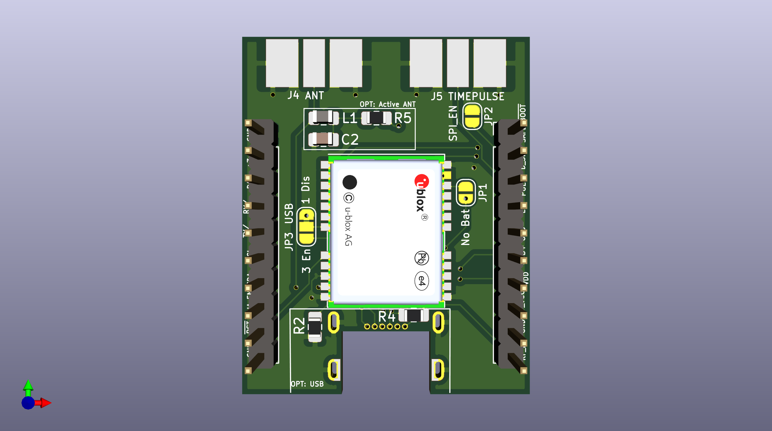
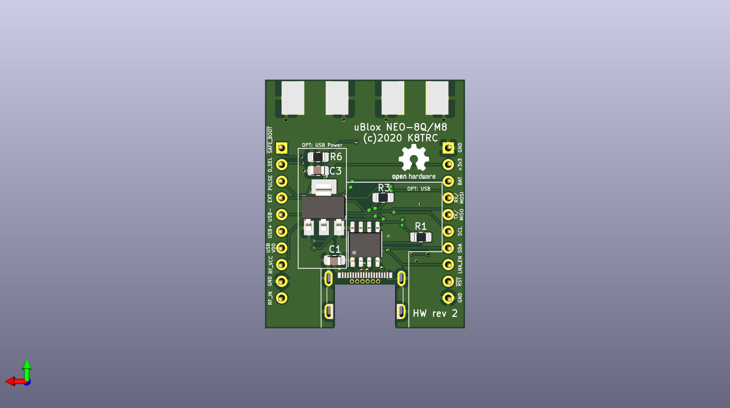
Neo8 adapter is an open-source printed circuit board by tclarke, from the tclarke/neo8_adapter repository on GitHub. It is a 2-layer board of 30.5 × 37.9 mm with 22 parts on 40 nets, routed with 238 tracks and 41 vias.
It is built around the LD1117S33CTR-HXY, USB6B1 and CX70M-24P1. Its parts include 6 resistors, 5 connectors, 3 capacitors, 3 ICs and 1 inductor. It belongs with the interfaces and adapters boards of this library.


This is a board designed to breakout pins on the uBlox NEO-8 GPS modules.
This design is licensed as Open Source Hardware

Initial revision of the board.
| Qty | Value | Footprint | References |
|---|---|---|---|
| 2 | 27 | Resistor_SMD:R_0805_2012Metric_Pad1.15x1.40mm_HandSolder | R1, R3 |
| 2 | 5.1k | Resistor_SMD:R_0805_2012Metric_Pad1.15x1.40mm_HandSolder | R2, R4 |
| 2 | HEADER_1X10 | Connector_PinHeader_2.54mm:PinHeader_1x10_P2.54mm_Vertical | J1, J3 |
| 1 | 10 | Resistor_SMD:R_0805_2012Metric_Pad1.15x1.40mm_HandSolder | R5 |
| 1 | 100k | Resistor_SMD:R_0805_2012Metric_Pad1.15x1.40mm_HandSolder | R6 |
| 1 | 100n | Capacitor_SMD:C_0805_2012Metric_Pad1.15x1.40mm_HandSolder | C1 |
| 1 | 10n | Capacitor_SMD:C_0805_2012Metric_Pad1.15x1.40mm_HandSolder | C2 |
| 1 | 10u | Capacitor_SMD:C_0805_2012Metric_Pad1.15x1.40mm_HandSolder | C3 |
| 1 | 27n | Inductor_SMD:L_0805_2012Metric_Pad1.15x1.40mm_HandSolder | L1 |
| 1 | ANT | digikey-footprints:RF_SMA_BoardEdge_142-0701-801 | J4 |
| 1 | CX70M-24P1 | digikey-footprints:USB-C_Female_CX70M-24P1 | J2 |
| 1 | LD1117S33CTR | digikey-footprints:SOT-223 | U3 |
| 1 | NEO-8Q | RF_GPS:ublox_NEO | U2 |
| 1 | No Bat | Jumper:SolderJumper-2_P1.3mm_Open_RoundedPad1.0x1.5mm | JP1 |
| 1 | SPI_EN | Jumper:SolderJumper-2_P1.3mm_Open_RoundedPad1.0x1.5mm | JP2 |
| 1 | TIMEPULSE | digikey-footprints:RF_SMA_BoardEdge_142-0701-801 | J5 |
| 1 | USB | Jumper:SolderJumper-3_P1.3mm_Bridged12_RoundedPad1.0x1.5mm_NumberLabels | JP3 |
| 1 | USB6B1 | Package_SO:SOIC-8_3.9x4.9mm_P1.27mm | U1 |
The 21 most common of 22 parts.


pardallabs/pardal_devStick32_typeC
Pardallabs Development Stick ESP32 Type C


youheng7185/xmos_xu316_cs43131_usb_aud
uac 2.0 on xmos xu316 with cs43131 audio codec
It measures 30.5 × 37.9 mm and has 2 copper layers, 1.6 mm thick.
22 parts, built around the LD1117S33CTR-HXY, USB6B1 and CX70M-24P1. The full list of its parts is on this page, with links to each part's symbol and footprint where PCBKit's library has them.
From the tclarke/neo8_adapter repository on GitHub, at the commit this page was made from: the board is neo8_adapter.kicad_pcb. PCBKit opens the board in the browser, with nothing to install.
Its repository states no licence, so its author keeps all rights: ask tclarke before reusing the design.