
4 layers71.8 × 40.5 mm

 tandej/pico-logic-analyzer
Pico logic analyzer is an open-source printed circuit board by tandej, from the tandej/pico-logic-analyzer repository on GitHub, published under the MIT licence. It is a 4-layer board of 57.5 × 57.5 mm with 48 parts on 86 nets, routed with 404 tracks and 119 vias.
It is built around the LM2665M6. Its parts include 9 capacitors, 8 diodes, 8 connectors, 5 ICs and 4 switches. It belongs with the sensors and measurement boards and the RP2040 boards of this library.
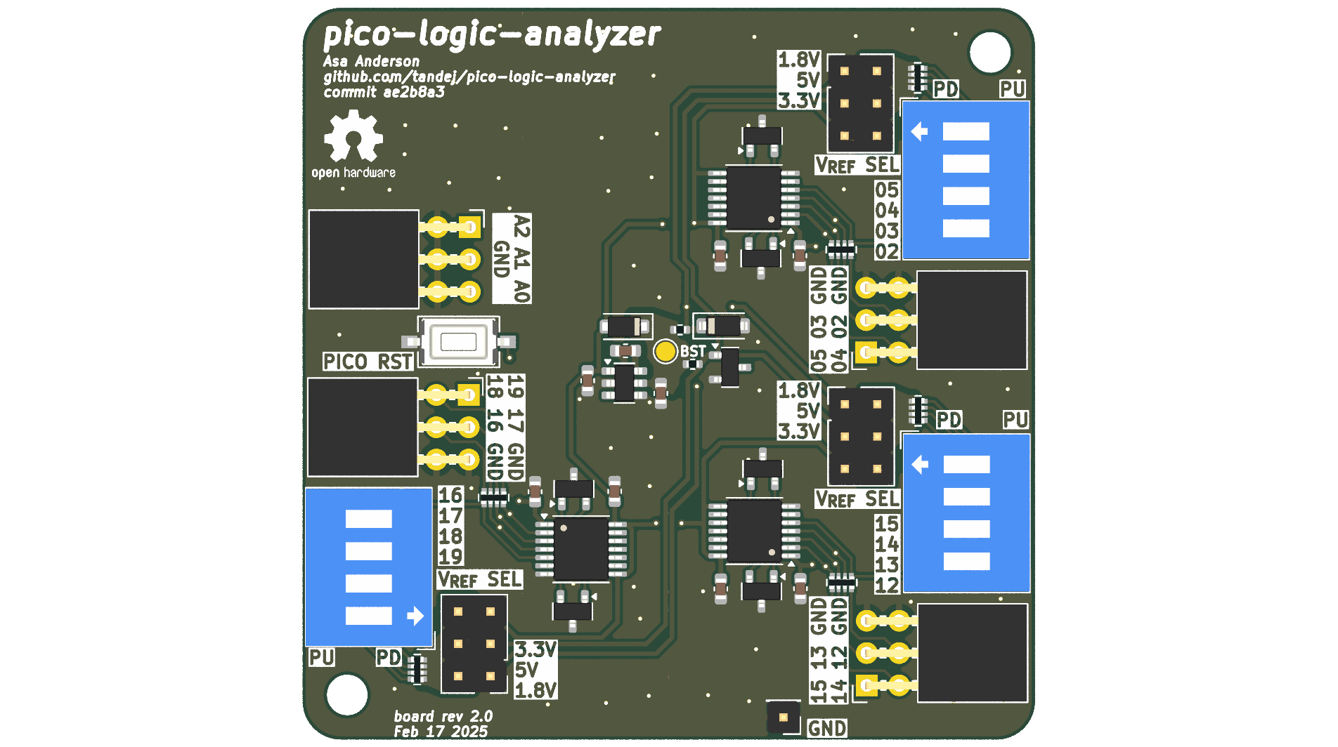
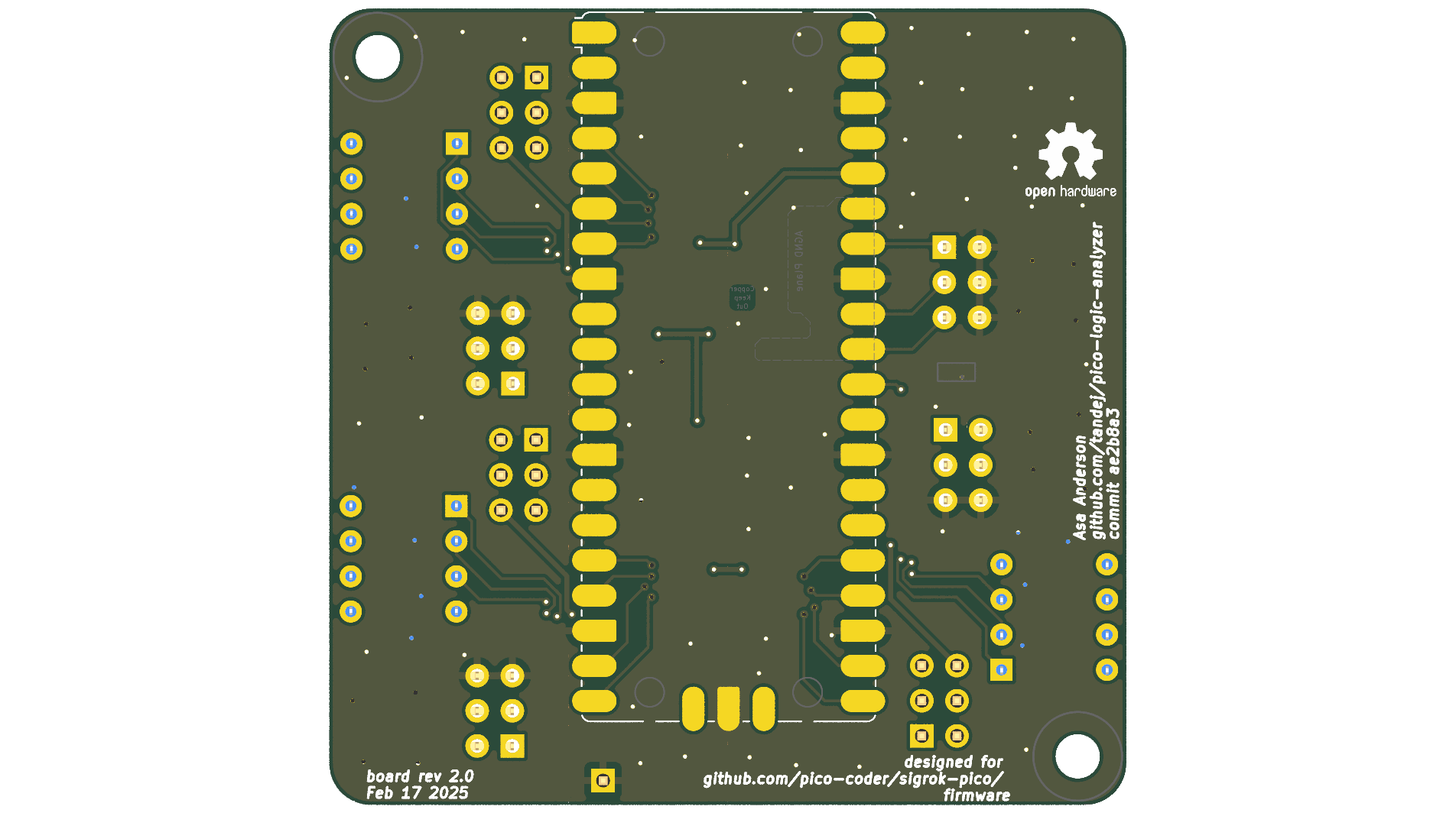
| Qty | Value | Footprint | References |
|---|---|---|---|
| 9 | 4.7 uF | Capacitor_SMD:C_0603_1608Metric | C1, C2, C3, C4, C5, C6, C7, C8, C9 |
| 6 | 6.2 V_{z}, prefer better tolerances | Package_TO_SOT_SMD:SOT-23 | D1, D2, D5, D6, D7, D8 |
| 4 | Conn_02x03_Odd_Even | Connector_PinSocket_2.54mm:PinSocket_2x03_P2.54mm_Horizontal | J2, J3, J4, J7 |
| 3 | 100k | Resistor_SMD:R_Array_Convex_4x0402 | RN1, RN3, RN6 |
| 3 | 470 | Resistor_SMD:R_Array_Convex_4x0402 | RN2, RN4, RN5 |
| 3 | Conn_02x03_Odd_Even | Connector_PinHeader_2.54mm:PinHeader_2x03_P2.54mm_Vertical | J1, J5, J6 |
| 3 | SW_DIP_x04 | Button_Switch_THT:SW_DIP_SPSTx04_Slide_9.78x12.34mm_W7.62mm_P2.54mm | SW1, SW3, SW4 |
| 3 | TXB0104PW (fit with U104) | Package_SO:TSSOP-14_4.4x5mm_P0.65mm | U1, U4, U5 |
| 2 | MountingHole | MountingHole:MountingHole_3.2mm_M3 | H1, H2 |
| 2 | oshw! | Symbol:OSHW-Logo2_7.3x6mm_SilkScreen | G1, G1 |
| 1 | 1.8v | Diode_SMD:D_SOD-123 | D4 |
| 1 | 100, >1/32 W | Resistor_SMD:R_0402_1005Metric | R2 |
| 1 | 1A 500 mV V_{F} | Diode_SMD:D_SOD-123F | D3 |
| 1 | 390, >1/10 W | Resistor_SMD:R_0402_1005Metric | R1 |
| 1 | Conn_01x01 | Connector_PinHeader_2.54mm:PinHeader_1x01_P2.54mm_Vertical | J8 |
| 1 | LM2665M6 | Package_TO_SOT_SMD:SOT-23-6 | U3 |
| 1 | LM4040DBZ-5 | Package_TO_SOT_SMD:SOT-23 | U2 |
| 1 | RaspberryPi_Pico | asa-lib:RaspberryPi_Pico_SMD | A1 |
| 1 | SW_Push | Button_Switch_SMD:SW_Tactile_SPST_NO_Straight_CK_PTS636Sx25SMTRLFS | SW2 |
| 1 | TestPoint | TestPoint:TestPoint_Pad_D1.5mm | TP1 |

GerritMihu/Advanced-Dice
Dice with USB-C, Chargepump, Li-Ion Batterie, Tilt-switch

Jsnchg/Heavy-Operations-UI-Industry-System-EI-SSCB

hackclub/OnBoard
💡 Join 1,000 teenagers and make your first PCB with a $100 grant!

LNH-team/Lost-NDS-TV
The Lost Nintendo DS Television Output, brought back to life


ccadic/sharpikeebo
Miniature RPI Zero 2W shield with Sharp memory Display and USB Beyboard
It measures 57.5 × 57.5 mm and has 4 copper layers, 1.6 mm thick.
48 parts, built around the LM2665M6. The full list of its parts is on this page, with links to each part's symbol and footprint where PCBKit's library has them.
From the tandej/pico-logic-analyzer repository on GitHub, at the commit this page was made from: the board is pico-logic-analyzer.kicad_pcb and its schematic buffer.kicad_sch. PCBKit opens the board in the browser, with nothing to install.
Its repository publishes it under the MIT licence: you may reuse it on that licence's terms (keep the author's notice, and for a copyleft licence share your changes alike).