2 layers51 × 51 mm

 taka-tuos/compatible-chan1
M5Stack compatible module for stack-chan
Compatible chan v0-led is an open-source printed circuit board by taka-tuos, from the taka-tuos/compatible-chan repository on GitHub, published under the GPL-3.0 licence. It is a 2-layer board of 51 × 51 mm with 19 parts on 43 nets, routed with 299 tracks and 90 vias.
It is built around the MAX7219M and 788BS. Its parts include 4 capacitors, 3 connectors, 2 resistors, 2 ICs and 2 diodes.

スタックチャン 用の自由なCoreモジュール (GPLv3)
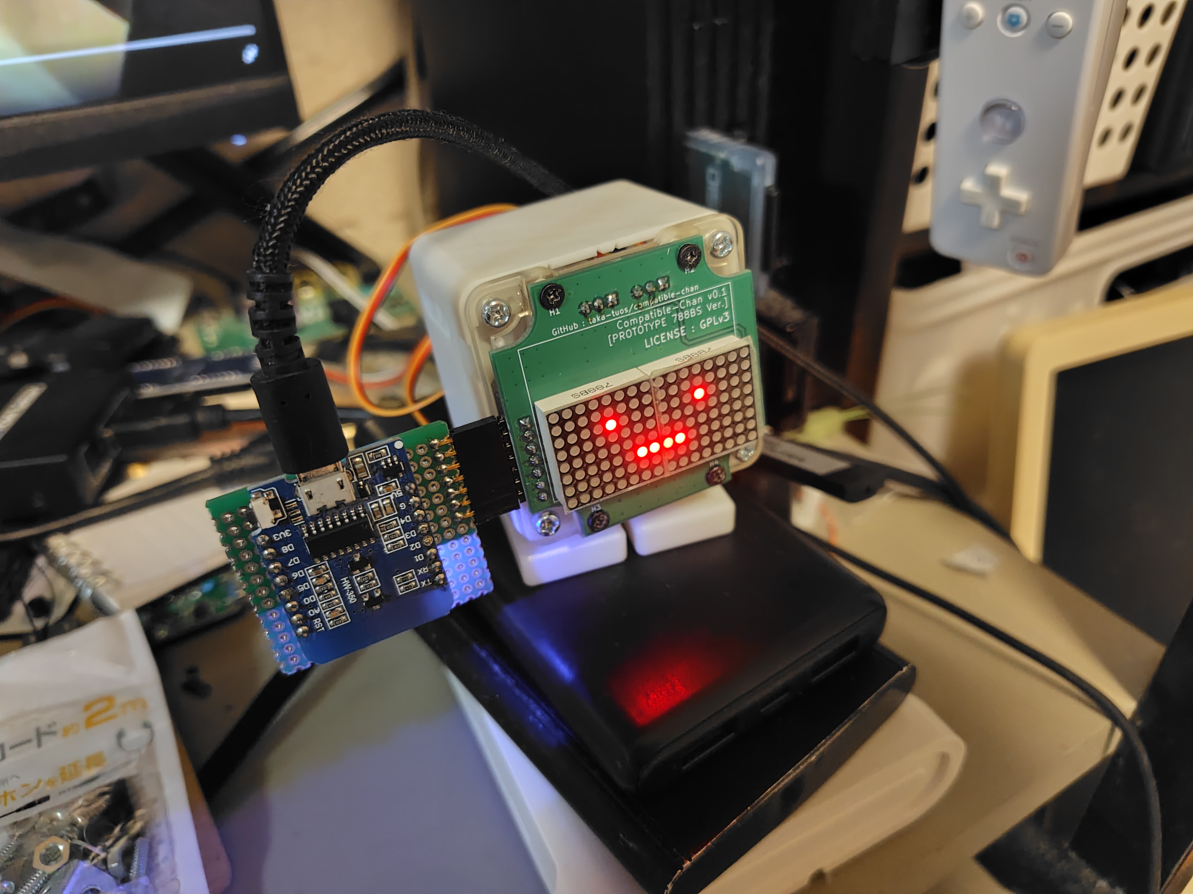
A. 各種ピン仕様や回路図こそオープンではあるが、シェルのCADデータやガーバーファイル、BOM等が公開されていないので「自由」ではない(と自分は考えている)。
A. スタックチャンは「サ終とともに死ぬロボットはアカン(意訳)」という思想を含んでいて^1、M5Stackの供給が止まると死ぬ状況はよろしくないはず。
(実際オンラインに依存していない旧AIBOシリーズでも、部品供給が無いのでバタバタ死んでいる)
またM5Stackの仕様に縛られる状況でその打開ができないのもよろしくない(よく挙がる例としてはスピーカーとマイクが排他なことなど)
| Qty | Value | Footprint | References |
|---|---|---|---|
| 4 | M2 | MountingHole:MountingHole_2.2mm_M2_DIN965_Pad | H1, H2, H3, H4 |
| 2 | 100n | Capacitor_SMD:C_0805_2012Metric_Pad1.18x1.45mm_HandSolder | C1, C2 |
| 2 | 10k | Resistor_THT:R_Axial_DIN0207_L6.3mm_D2.5mm_P10.16mm_Horizontal | R1, R2 |
| 2 | 10u | Capacitor_Tantalum_SMD:CP_EIA-2012-15_AVX-P_Pad1.30x1.05mm_HandSolder | C3, C4 |
| 2 | 788BS | akn_misc:LED_8x8_1.9MM_20x20MM | D1, D2 |
| 2 | MAX7219 | Package_SO:SOIC-24W_7.5x15.4mm_P1.27mm | U1, U2 |
| 1 | EXT | Connector_PinHeader_2.54mm:PinHeader_1x07_P2.54mm_Horizontal | J1 |
| 1 | SERVO1 | Connector_PinHeader_2.54mm:PinHeader_1x03_P2.54mm_Vertical | J2 |
| 1 | SERVO2 | Connector_PinHeader_2.54mm:PinHeader_1x03_P2.54mm_Vertical | J3 |
The 17 most common of 19 parts.

taka-tuos/compatible-chan
M5Stack compatible module for stack-chan

StarGate01/hl-alyx-glove
Firmware and Hardware for a Half-Life: Alyx Gravity Glove Replica


shanteacontrols/OpenDeck
A platform for building interactive control and sensing devices using MIDI and OSC built with Zephyr RTOS.


Eigenbaukombinat/glowboard
The Glowboard Plotter plots images using 64 UV LEDs attached in a line moved over a 120cmx60cm glow-in-the-dark sheet by a stepper.


It measures 51 × 51 mm and has 2 copper layers, 1.6 mm thick.
19 parts, built around the MAX7219M and 788BS. The full list of its parts is on this page, with links to each part's symbol and footprint where PCBKit's library has them.
From the taka-tuos/compatible-chan repository on GitHub, at the commit this page was made from: the board is compatible-chan-v0-led/compatible_chan-v0-led.kicad_pcb and its schematic compatible-chan-v0-led/compatible_chan-v0-led.kicad_sch. PCBKit opens the board in the browser, with nothing to install.
Its repository publishes it under the GPL-3.0 licence: you may reuse it on that licence's terms (keep the author's notice, and for a copyleft licence share your changes alike).