2 layers75.5 × 61 mm
 synfinatic/delaytimer
12V/2A Adjustable Delay Timer
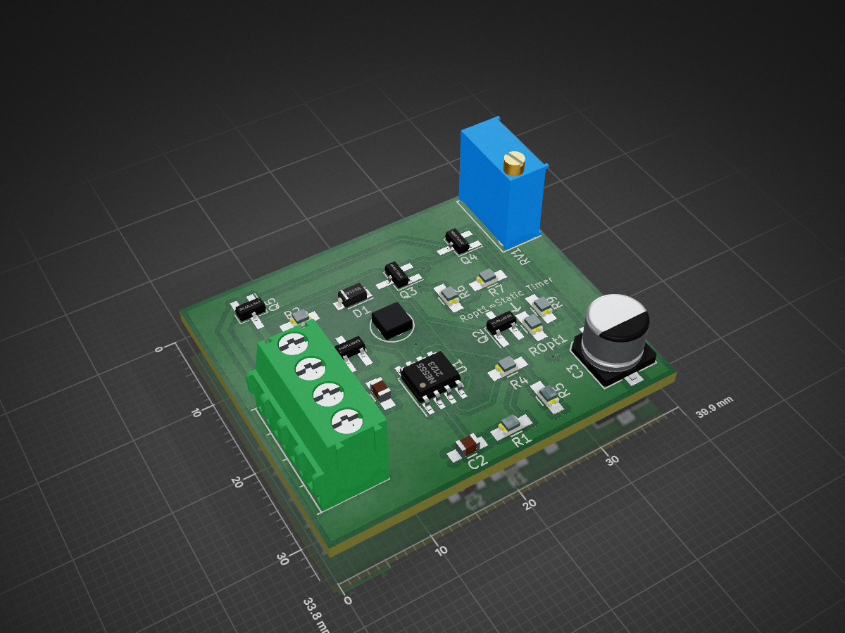
Delaytimer is an open-source printed circuit board by synfinatic, from the synfinatic/delaytimer repository on GitHub. It is a 2-layer board of 39.9 × 33.8 mm with 22 parts on 15 nets, routed with 129 tracks and 5 vias.
It is built around the NE555, MMBT3904 and MMBT3906, with the IRLML6344 among its other parts. Its parts include 9 resistors, 5 transistors, 3 capacitors, 1 IC and 1 diode.


This is a simple adjustable power-off delay timer supporting 5-12V DC and up to 2A.
When the power is turned on (both 12V and Switch are "on") then Output is also on. When Switch is "off", then a timer starts. When the timer expires (0-55 seconds) then Output is turned off.
Copyright 2017 Aaron Turner
This project is licensed under the GPLv3.
Special thanks to Rob Paisley who helped with the circuit design.
| Qty | Value | Footprint | References |
|---|---|---|---|
| 4 | 2.2k | Resistors_SMD:R_0805_HandSoldering | R2, R5, R7, R8 |
| 2 | 0.1uf | Capacitors_SMD:C_0805_HandSoldering | C1, C2 |
| 2 | 100k | Resistors_SMD:R_0805_HandSoldering | R1, ROpt1 |
| 2 | 10k | Resistors_SMD:R_0805_HandSoldering | R4, R6 |
| 2 | MMBT3904 | TO_SOT_Packages_SMD:SOT-23_Handsoldering | Q1, Q2 |
| 2 | MMBT3906 | TO_SOT_Packages_SMD:SOT-23_Handsoldering | Q3, Q4 |
| 1 | Connectors:1pin | ||
| 1 | 100uf | Capacitors_SMD:c_elec_6.3x7.7 | C3 |
| 1 | 1k | Resistors_SMD:R_0805_HandSoldering | R9 |
| 1 | 1n4148 | Diodes_SMD:SOD-123 | D1 |
| 1 | 500k | Potentiometers:Potentiometer_Bourns_3296W_3-8Zoll_Inline_ScrewUp | RV1 |
| 1 | CONN_01X04 | Connectors_Terminal_Blocks:TerminalBlock_Pheonix_PT-3.5mm_4pol | P1 |
| 1 | IRLML6344 | TO_SOT_Packages_SMD:SOT-23_Handsoldering | Q5 |
| 1 | NE555 | Housings_SOIC:SOIC-8_3.9x4.9mm_Pitch1.27mm | U1 |
It measures 39.9 × 33.8 mm and has 2 copper layers, 1.6 mm thick.
22 parts, built around the NE555, MMBT3904, MMBT3906 and IRLML6344. The full list of its parts is on this page, with links to each part's symbol and footprint where PCBKit's library has them.
From the synfinatic/delaytimer repository on GitHub, at the commit this page was made from: the board is kicad/delaytimer.kicad_pcb. PCBKit opens the board in the browser, with nothing to install.
Its repository states no licence, so its author keeps all rights: ask synfinatic before reusing the design.


nodep/NovaBox
Circuit and PCB design of simple Bluetooth stereo receiver and amplifier

kraakenstuff/ADSR
2HP ADSR module based on "Fastest Envelope in the West" by René Schmitz (https://www.schmitzbits.de/adsr.html)

iamtsb/systest-joystick-dongle
I’m repairing lots of Amiga machines, and my (original) joystick connectors where failing after they have been swapped between all those machines.


timex-sinclair-projects/tspico-hardware
Status 2026-10-19: prototype 3 (v3.0-proto3, changes below). Proto1 (v3.0-proto1) was built and brought up; proto2 added its fixes (below).

fossasia/pslab-hardware
PSLab Hardware Design and Schematics https://pslab.io