2 layers142.5 × 106.4 mm
 SwiftDust/binary-adder1
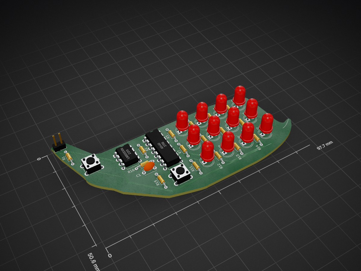
A binary adder PCB utilising the 555 and CD4060.
Binary adder is an open-source printed circuit board by SwiftDust, from the SwiftDust/binary-adder repository on GitHub. It is a 2-layer board of 98 × 51 mm with 34 parts on 32 nets, routed with 216 tracks and 1 via.
Its parts include 16 resistors, 12 diodes, 2 ICs, 2 switches and 1 capacitor.
This is a simple binary adder in the form of an Airbus Beluga. It is a simple project for me to learn how to use ICs. This is for Resolution Week 3 but a new rule states you can't use monorepos so that's why I made this separate repository.
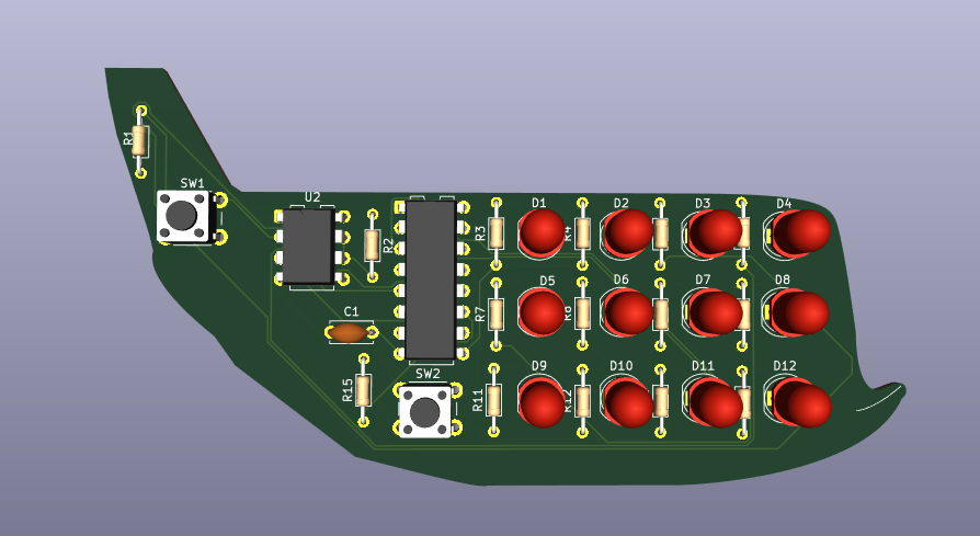
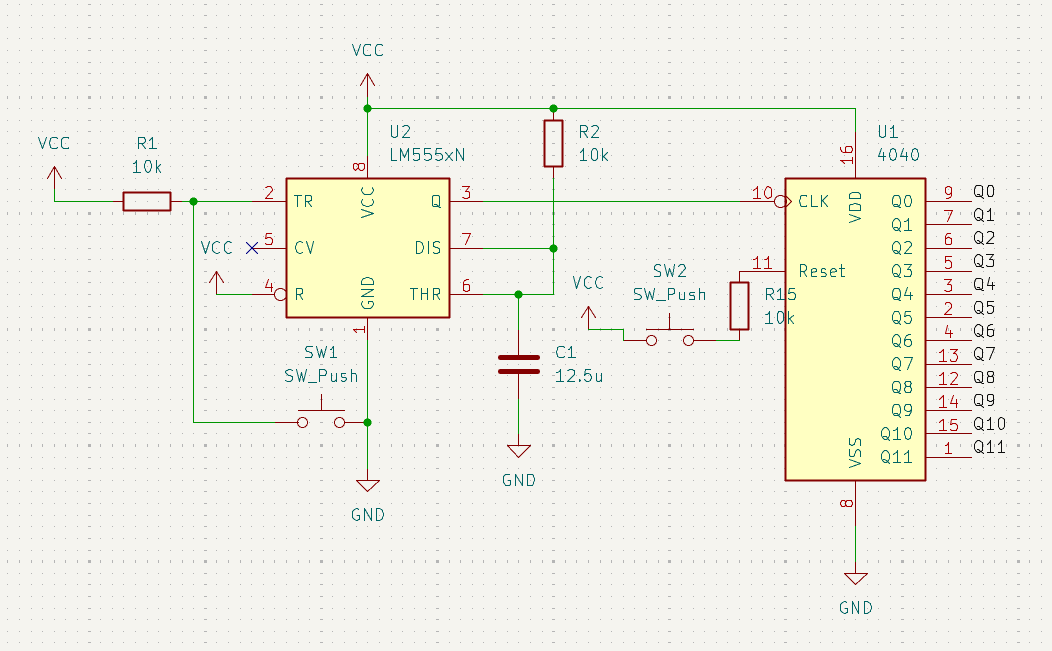
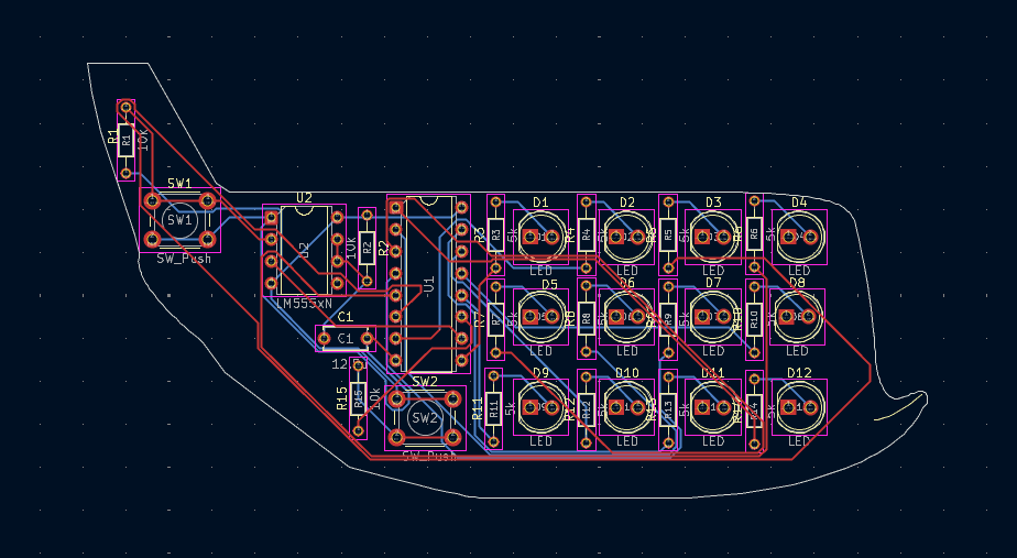
I used the well-known 555 and CD4060 to make this PCB. I used the 555 in monostable mode with a time constant of 0.125 seconds. This is derived by the fact that the average person would click on a button no more than eight times in a second, so a time constant of 0.125 or lower is required. If we make the time constant too low, it may not be fed correctly into the 4060, so that is why I chose this value. The input of the 555 is wired to a button. The CLK input of the 4060 is then wired up with the output of the 555 and all the outputs are wired to LEDs. If the output of the 555 is high, the binary adder will add one number to the output. Additionally, I have added a "Reset" button wired to the RST input of the 4060, so people can reset the counter. I made this PCB for fun, but can be useful to learn to count in binary too!
| Qty | Value | Footprint | References |
|---|---|---|---|
| 12 | 5k | Resistor_THT:R_Axial_DIN0204_L3.6mm_D1.6mm_P7.62mm_Horizontal | R3, R4, R5, R6, R7, R8, R9, R10, R11, R12, R13, R14 |
| 12 | LED | LED_THT:LED_D5.0mm | D1, D2, D3, D4, D5, D6, D7, D8, D9, D10, D11, D12 |
| 4 | 10k | Resistor_THT:R_Axial_DIN0204_L3.6mm_D1.6mm_P7.62mm_Horizontal | R1, R2, R15, R16 |
| 2 | SW_Push | Button_Switch_THT:SW_PUSH_6mm | SW1, SW2 |
| 1 | 12.5u | Capacitor_THT:C_Disc_D5.0mm_W2.5mm_P5.00mm | C1 |
| 1 | 4040 | Package_DIP:DIP-16_W7.62mm | U1 |
| 1 | Conn_01x02 | Connector_PinHeader_2.54mm:PinHeader_1x02_P2.54mm_Vertical | J1 |
| 1 | LM555xN | Package_DIP:DIP-8_W7.62mm | U2 |
It measures 98 × 51 mm and has 2 copper layers, 1.6 mm thick.
34 parts. The full list of its parts is on this page, with links to each part's symbol and footprint where PCBKit's library has them.
From the SwiftDust/binary-adder repository on GitHub, at the commit this page was made from: the board is Schematics/binary_adder.kicad_pcb and its schematic Schematics/binary_adder.kicad_sch. PCBKit opens the board in the browser, with nothing to install.
Its repository states no licence, so its author keeps all rights: ask SwiftDust before reusing the design.

FrameworkComputer/ExpansionCards
Reference designs and documentation to create Expansion Cards for the Framework Laptop

mntmn/amiga2000-gfxcard
MNT VA2000, an Open Source Amiga 2/3/4000 Graphics Card (Zorro II/III), written in Verilog

hackclub/OnBoard
💡 Join 1,000 teenagers and make your first PCB with a $100 grant!


strangeparts/niubi-headphones
Flexible circuit board design for adding a headphone jack to an iPhone 7


baldengineer/bit-preserve
Project for capturing vintage, classic, aka old computer schematics in KiCad.