
2 layers40.6 × 110 mm
Europi surface mount
Allen-Synthesis/EuroPi
EuroPi: A reprogrammable Eurorack module based on the Raspberry Pi Pico
92 parts584CC0-1.0

 swalberg/antennaswitch1
Controller for a 12v 4 port antenna switch
RemoteAntennaSwitch is an open-source printed circuit board by swalberg, from the swalberg/antennaswitch repository on GitHub. It is a 2-layer board of 73.5 × 51.5 mm with 27 parts on 47 nets, routed with 121 tracks and 0 vias.
It is built around the L7805. Its parts include 12 resistors, 8 transistors, 4 connectors, 2 capacitors and 1 IC. It belongs with the radio and wireless boards and the ESP8266 boards of this library.
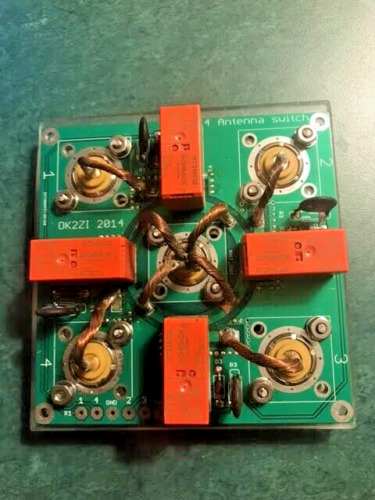
This is a remote controller for one of those DIY antenna switch kits. It listens on Wifi for commands and controls the relays. They take a +12V signal to one of 4 relays with a common ground to pick which port is active, and ground the rest:
The firmware for this allows both manual control, and to listen to N1MM+/RUMLogNG broadcasts to pick the band based on configured port/band combinations.
Manual control - go to the web and select the port you want
Auto selection - listens on 12060/UDP for station messages indicating the frequency. You select the antennas that work on each port and it picks the first one. If you go to the web and override it, it'll last until you switch bands.
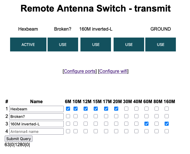
When the device boots without a config it'll start a new AP for you to configure it.
| Qty | Value | Footprint | References |
|---|---|---|---|
| 8 | R47k | Resistor_THT:R_Axial_DIN0207_L6.3mm_D2.5mm_P10.16mm_Horizontal | R2, R3, R5, R6, R8, R9, R11, R12 |
| 4 | 2N4401 | Package_TO_SOT_THT:TO-92_Wide | Q1, Q3, Q5, Q7 |
| 4 | 2N4403 | Package_TO_SOT_THT:TO-92_Wide | Q2, Q4, Q6, Q8 |
| 4 | R1k | Resistor_THT:R_Axial_DIN0204_L3.6mm_D1.6mm_P5.08mm_Vertical | R1, R4, R7, R10 |
| 1 | C | Capacitor_THT:C_Disc_D3.0mm_W1.6mm_P2.50mm | C1 |
| 1 | C_Polarized_US | Capacitor_THT:CP_Radial_D4.0mm_P2.00mm | C2 |
| 1 | Conn_01x02_Pin | Connector_PinHeader_2.54mm:PinHeader_1x02_P2.54mm_Vertical | J4 |
| 1 | Conn_01x05_Pin | Connector_JST:JST_EH_B5B-EH-A_1x05_P2.50mm_Vertical | J1 |
| 1 | ESP8266_LEFT | Connector_PinHeader_2.54mm:PinHeader_1x15_P2.54mm_Vertical | J2 |
| 1 | ESP8266_RIGHT | Connector_PinHeader_2.54mm:PinHeader_1x15_P2.54mm_Vertical | J3 |
| 1 | L7805 | Package_TO_SOT_THT:TO-220-3_Vertical | U1 |
Allen-Synthesis/EuroPi
EuroPi: A reprogrammable Eurorack module based on the Raspberry Pi Pico

peterheinrich/InternetOverSpaghetti
Transmitting IP packages over a pair of spaghetti thus demonstrating how media independent IP really is.


Tircown/ERCF-easy-brd
More informations on how to reset for flashing:\ https://wiki.seeedstudio.com/Seeeduino-XIAO/#enter-bootloader-mode

matthewcieplak/super-sixteen
Code and schematics for the Super Sixteen Eurorack sequencer

NikodemBartnik/Mini-Mars-Rover
Educational robotic platform made to look like a mini mars rover

starlightk7/OpenSFC
OSHW Reproduction Parts related to the Super Famicom / Super Nintendo game console

Redherring32/OpenTendo-TopLoader
An Open Source HardWare (OSHW) recreation of the 1993 toploading NES motherboard (Also known as NES-101)
It measures 73.5 × 51.5 mm and has 2 copper layers, 1.6 mm thick.
27 parts, built around the L7805. The full list of its parts is on this page, with links to each part's symbol and footprint where PCBKit's library has them.
From the swalberg/antennaswitch repository on GitHub, at the commit this page was made from: the board is kicad/RemoteAntennaSwitch.kicad_pcb and its schematic kicad/RemoteAntennaSwitch.kicad_sch. PCBKit opens the board in the browser, with nothing to install.
Its repository states no licence, so its author keeps all rights: ask swalberg before reusing the design.