

Sensor HW
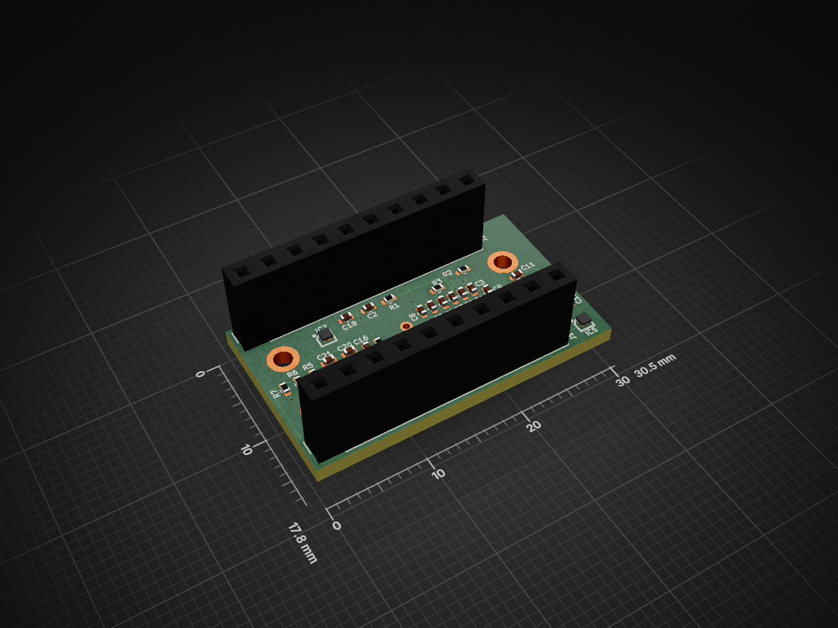
- Size
- 30.5 × 17.8 mm
- Copper layers
- 4
- Thickness
- 1.6 mm
- Parts
- 44
- Nets
- 50
- Pads
- 165
- Tracks, vias
- 336, 37
- Pours
- 2
- Routed
- Yes
- KiCad
- KiCad 8.0 (file 20240108)
- Created
- 14 Apr 2025
- Updated
- 30 Apr 2025
Overview
Sensor is an open-source printed circuit board by sugar-sensor, from the sugar-sensor/sensor-schematics repository on GitHub, published under the MIT licence. It is a 4-layer board of 30.5 × 17.8 mm with 44 parts on 50 nets, routed with 336 tracks and 37 vias.
It is built around the MAX86141ENP+T, MAX30002CWV+T and CC0402MRX5R5BB106, with the CC0402KRX5R5BB105, CRCW04020000Z0EDC and CC0402KRX5R5BB104 among its other parts. Its parts include 21 capacitors, 9 resistors, 6 connectors, 5 ICs and 3 diodes. It belongs with the sensors and measurement boards of this library.
Main components
12MAX86141ENP+T
WLP-20(2x1.8)-40℃~+85℃ 1.17mA 1.7V~2V 19bit 3 Integrated ambient light cancellation (ALC)、Built-in temperature sensor SPI WLP-20(2x1.8) Specialized Sensors ROHSMaxim Integrated (Analog Devices)Heart Rate SensorsMAX30002CWV+T
WLP-30(2.7x2.9)0℃~+70℃ 1 1.1V~2V 104.9dB 20 Programmable gain、Fault detection、ESD protection WLP-30(2.7x2.9) Analog Front End (AFE) ROHSMaxim Integrated (Analog Devices)Analog Front End (AFEs)CC0402MRX5R5BB106
040210uF 6.3V X5R ±20% 0402 Multilayer Ceramic Capacitors MLCC - SMD/SMT ROHSYAGEOMultilayer Ceramic Capacitors MLCC - SMD/SMTCC0402KRX5R5BB105
04021uF 6.3V X5R ±10% 0402 Multilayer Ceramic Capacitors MLCC - SMD/SMT ROHSYAGEOMultilayer Ceramic Capacitors MLCC - SMD/SMTCRCW04020000Z0EDC
0402-55℃~+155℃ 0Ω 50V 62.5mW Thick Film Resistor 0402 Chip Resistor - Surface Mount ROHSVishay IntertechnologyChip Resistor - Surface MountCC0402KRX5R5BB104
0402100nF 6.3V X5R ±10% 0402 Multilayer Ceramic Capacitors MLCC - SMD/SMT ROHSYAGEOMultilayer Ceramic Capacitors MLCC - SMD/SMTCRCW04021K00FKEDC
0402-55℃~+155℃ 1kΩ 50V 62.5mW Thick Film Resistor ±1% ±100ppm/℃ 0402 Chip Resistor - Surface Mount ROHSVishay IntertechnologyChip Resistor - Surface MountCC0402KRNPO7BN100
040210pF 16V NP0 ±10% 0402 Multilayer Ceramic Capacitors MLCC - SMD/SMT ROHSYAGEOMultilayer Ceramic Capacitors MLCC - SMD/SMTCRCW0402200RFKEDC
0402-55℃~+155℃ 200Ω 50V 62.5mW Thick Film Resistor ±1% ±100ppm/℃ 0402 Chip Resistor - Surface Mount ROHSVishay IntertechnologyChip Resistor - Surface MountCC0402KRX5R6BB473
040210V 47nF X5R ±10% 0402 Multilayer Ceramic Capacitors MLCC - SMD/SMT ROHSYAGEOMultilayer Ceramic Capacitors MLCC - SMD/SMTVEMD8081
SMD-8P-40℃~+85℃ 20V 350nm~1100nm 500pA 65° 840nm SMD-8P Photodiodes ROHSVishay IntertechnologyPhotodiodesCC0402JRNPO7BN102
040216V 1nF ±5% 0402 Multilayer Ceramic Capacitors MLCC - SMD/SMT ROHSYAGEOMultilayer Ceramic Capacitors MLCC - SMD/SMT
README
README.mdDescription
Electrical and mechanical schematics for sugar sensor. Includes PCB design and BOM + Gerber files for sensor production Repository has 2 branches: v1 and v2. Both are based on MAX86141 AFE to work with LEDs. The difference between v1 and v2 are the following:
- v1 uses 3 LEDS (RED, GREEN, BLUE) as light source (non-coherent) while v2 uses 7mW 650nm RED laser (coherent)
- v1 uses AD5933 BioZ controller while v2 uses MAX30002 BioZ controller
- in v2 the main board dependency is removed. Main board replaced with external TinyPICO board and add-ons. Sensor board is stackable
Project notes
- The main reason to move from v1 to v2 of the sensor board is failed tests on non-coherent light sources. "Failed" means prediction based on these measurements didn't work.
- Version 2 deprecates "main" folder with all the schematics for main board (controller). Sensor board is stacked with TiniPICO development board and it is stacked with RGB IPS Display shield from add-ons menu.
- Sensor board programming, testing and obtaining the results is done using MAX32630FHTR application platform. Development was done in Mbed Studio
Structure
- hull for the wearable device
- lib is custom libraries for KiCad
- main is a mainboad schematics. Valid only for v1. Not tested and not produced.
- mech is 3D models for the KiCad component representation on PCB
- sensor is sensor schematic, board, BOM, gerbers for production. Both versions were tested and produced
Parts
44| Qty | Value | Footprint | References |
|---|---|---|---|
| 6 | 10uF | Capacitor_SMD:C_0402_1005Metric | C5, C8, C12, C13, C16, C20 |
| 6 | 1uF | Capacitor_SMD:C_0402_1005Metric | C4, C14, C15, C17, C18, C21 |
| 4 | Probe_01_male | Horace:Probe_01_male | J3, J4, J5, J6 |
| 3 | 0 | Resistor_SMD:R_0402_1005Metric | R4, R8, R9 |
| 3 | 0.1uF | Capacitor_SMD:C_0402_1005Metric | C9, C10, C19 |
| 3 | 1k | Resistor_SMD:R_0402_1005Metric | R5, R6, R7 |
| 2 | 10pF | Capacitor_SMD:C_0402_1005Metric | C1, C2 |
| 2 | 200 | Resistor_SMD:R_0402_1005Metric | R1, R2 |
| 2 | 47nF | Capacitor_SMD:C_0402_1005Metric | C6, C7 |
| 2 | Conn_01x10_Female | Connector_PinSocket_2.54mm:PinSocket_1x10_P2.54mm_Vertical | J1, J2 |
| 2 | VEMD8081 | Horace:VEMD8081 | D2, D3 |
| 1 | 1nF | Capacitor_SMD:C_0402_1005Metric | C11 |
| 1 | 324k | Resistor_SMD:R_0402_1005Metric | R3 |
| 1 | 47pF | Capacitor_SMD:C_0402_1005Metric | C3 |
| 1 | LP5900TLX-1.8_NOPB | Horace:BGA4C50P2X2_105X108X68 | IC5 |
| 1 | LP5900TLX-2.7_NOPB | Horace:BGA4C50P2X2_105X108X68 | IC2 |
| 1 | MAX30002CWV+ | Horace:MAX30002CWV | IC1 |
| 1 | MAX86141ENP+T | Horace:BGA20C40P5X4_205X185X50 | IC3 |
| 1 | RLD65NZX1-00A | Horace:RLD85PZJ400A | D1 |
| 1 | SIT1532AC | Horace:SIT1532ACJ5DCC32768D | IC4 |
Questions
How big is the Sensor PCB?
It measures 30.5 × 17.8 mm and has 4 copper layers, 1.6 mm thick.
What parts does the Sensor use?
44 parts, built around the MAX86141ENP+T, MAX30002CWV+T, CC0402MRX5R5BB106 and CC0402KRX5R5BB105. The full list of its parts is on this page, with links to each part's symbol and footprint where PCBKit's library has them.
Where can I download the Sensor KiCad files?
From the sugar-sensor/sensor-schematics repository on GitHub, at the commit this page was made from: the board is sensor/sensor.kicad_pcb and its schematic sensor/sensor.kicad_sch. PCBKit opens the board in the browser, with nothing to install.
Can I use the Sensor design in my own project?
Its repository publishes it under the MIT licence: you may reuse it on that licence's terms (keep the author's notice, and for a copyleft licence share your changes alike).
More from sugar-sensor/sensor-schematics
1- 6 layers18.3 × 36.1 mm
Similar boards
- 8 layers90.5 × 49.5 mm

- 4 layers46 × 46 mm

- 4 layers220 × 120 mm

Candidate filled profile
misko/prompt2device
The separate vNext PCB skill and orchestrator package is available alongside the reference workflow below; existing projects keep their accepted toolchain until an explicit migration.
569 parts3MIT - 6 layers

Pc healthypi move sensor v9
Protocentral/healthypi-move-hw
Hardware files for the HealthyPi Move
124 parts160MIT - 2 layers100 × 65 mm

- 4 layers80 × 60 mm

- 4 layers35 × 55.3 mm

- 2 layers101 × 76 mm
