2 layers141.9 × 72.9 mm
Imu to dxl 10p
jyg9/microduck-community-kit
补充microduck缺少的硬件电路和固件,另外配套一些测试工具。imu_to_dxl;banana_pcb;microduck复刻
897 parts28Apache-2.0
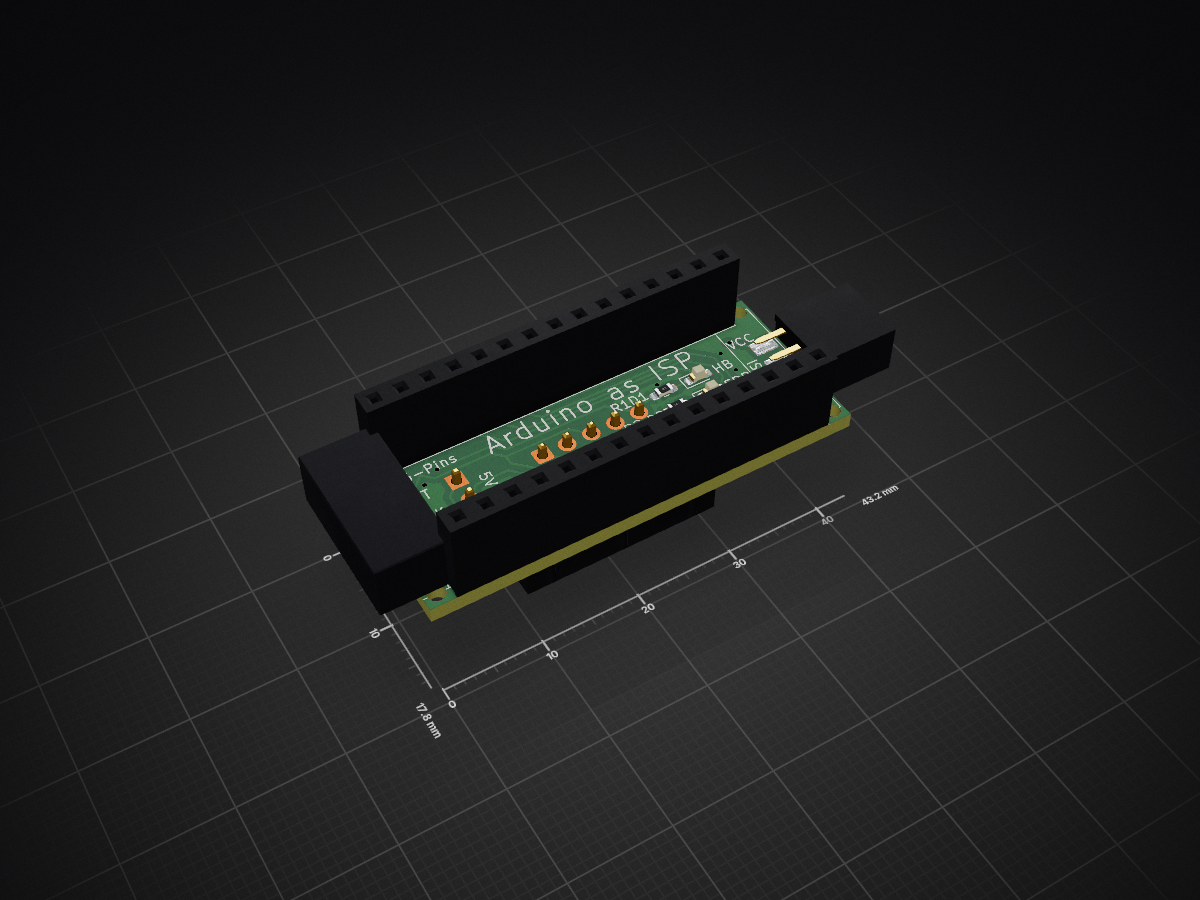
 stonedDiscord/ArduinoISP
A PCB to use an Arduino Nano as an In-Circuit Serial Programmer (ISP) for programming AVR microcontrollers.
ArduinoISP is an open-source printed circuit board by stonedDiscord, from the stonedDiscord/ArduinoISP repository on GitHub, published under the BSD-2-Clause licence. It is a 2-layer board of 43.2 × 17.8 mm with 16 parts on 34 nets, routed with 122 tracks and 16 vias.
It is built around the FRC0603F2200TS, 2541WV-03P and 2541FV-15P-B, with the GL0603UR01, GL0603UG01 and DS1013-10SSIB1-B-0 among its other parts. Its parts include 5 connectors, 3 resistors and 3 diodes. It belongs with the interfaces and adapters boards of this library.


A PCB to use an Arduino Nano as an In-Circuit Serial Programmer (ISP) for programming AVR microcontrollers.
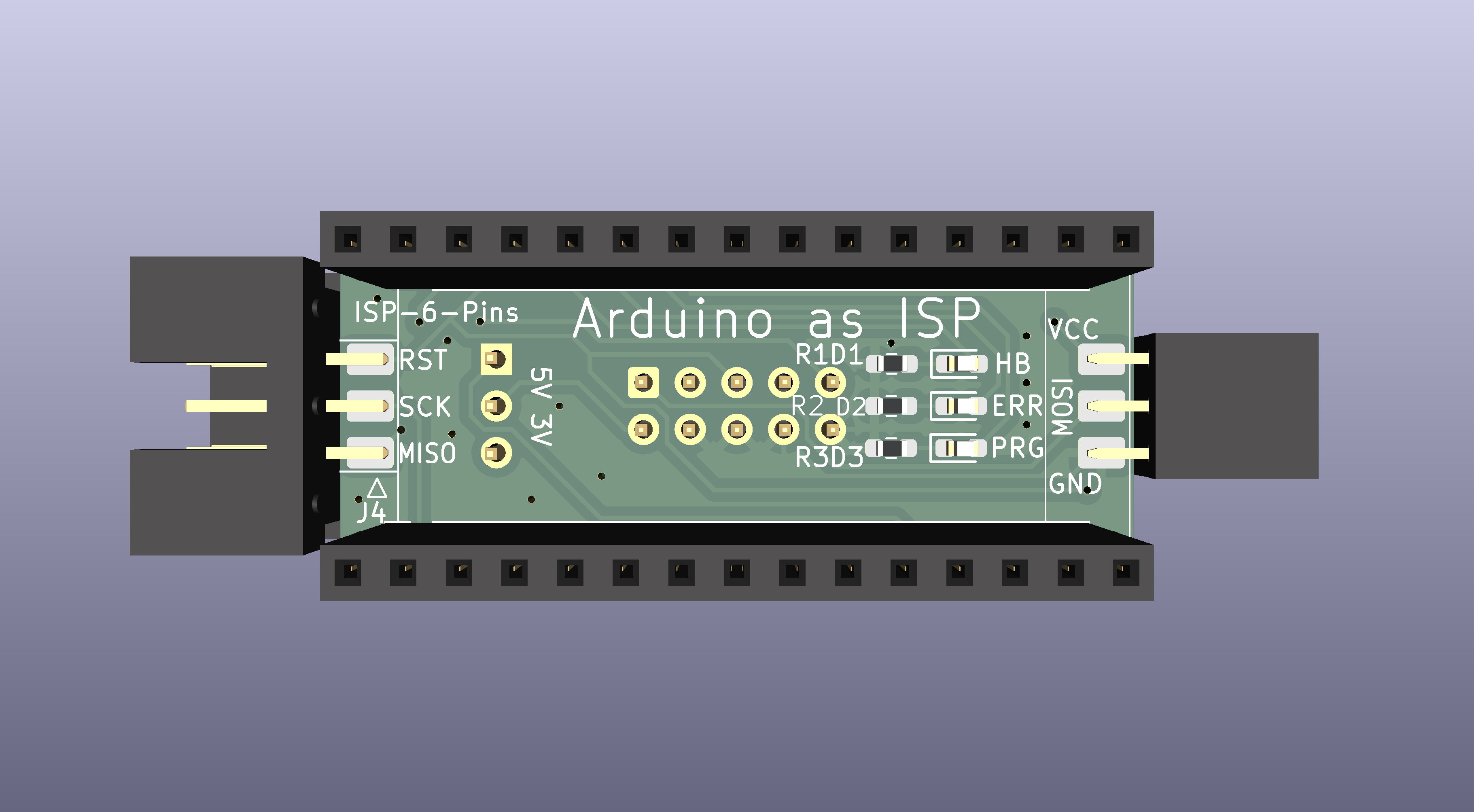
This board makes it easier for an Arduino Nano to function as an ISP programmer, enabling you to burn bootloaders to other Arduinos and program AVR chips like the ATmega series, or ATtiny microcontrollers. To do that, it connects the Arduino Nano correctly to the microcontroller's SPI pins (MOSI, MISO, SCK) and reset pin. The board is designed in a way that the 6-pin socket header can be directly soldered to the board vertically, while the 10-pin header can accept a flat cable with an adapter on the other end, similiar to the many USBASP clones.
The PCB includes:
The ISP programming uses the following connections from the Nano to the 6-pin ICSP connector:
| ISP Pin | Signal | Nano Pin |
|---|---|---|
| 1 | MISO | D12 |
| 2 | VCC | +5V |
| 3 | SCK | D13 |
| 4 | MOSI | D11 |
| 5 | RST | D10 |
| 6 | GND | GND |
The standard ICSP header pinout looks like this, with the key (if present) next to SCK
| MISO | VCC |
| ] SCK | MOSI |
| RST | GND |
File > Examples > 11.ArduinoISP > ArduinoISPYou can also find the sketch on the official Arduino GitHub page
Connect the Nano to this PCB's headers. The board will provide the 6-pin ISP connector for connecting to your target device.
Tools > BoardArduino as ISP in Tools > ProgrammerTools > Burn BootloaderThis project is participating in the 2026 Kicad PCB Design Contest. You can check out the project on the PCBway website.
| Qty | Value | Footprint | References |
|---|---|---|---|
| 4 | MountingHole_65mil | ArduinoISP:MountingHole_65mil | MH1, MH2, MH3, MH4 |
| 3 | 220 | Resistor_SMD:R_0603_1608Metric_Pad0.98x0.95mm_HandSolder | R1, R2, R3 |
| 1 | 5V 3V | Connector_PinHeader_2.54mm:PinHeader_1x03_P2.54mm_Vertical | JP1 |
| 1 | Analog | Connector_PinSocket_2.54mm:PinSocket_1x15_P2.54mm_Vertical | J1 |
| 1 | Digital | Connector_PinSocket_2.54mm:PinSocket_1x15_P2.54mm_Vertical | J2 |
| 1 | ERR | LED_SMD:LED_0603_1608Metric_Pad1.05x0.95mm_HandSolder | D2 |
| 1 | HB | LED_SMD:LED_0603_1608Metric_Pad1.05x0.95mm_HandSolder | D1 |
| 1 | ISP-10 | Connector_IDC:IDC-Header_2x05_P2.54mm_Vertical | J3 |
| 1 | ISP-6-Pins | ArduinoISP:IDC-Header_2x03_P2.54mm_Horizontal | J4 |
| 1 | ISP-6-Socket | ArduinoISP:IDC-Header_2x03_P2.54mm_Horizontal | J5 |
| 1 | PRG | LED_SMD:LED_0603_1608Metric_Pad1.05x0.95mm_HandSolder | D3 |
jyg9/microduck-community-kit
补充microduck缺少的硬件电路和固件,另外配套一些测试工具。imu_to_dxl;banana_pcb;microduck复刻


Sealflux/PCB_Business_Card
A business card that lights up when you tap it with your phone. No battery. It just steals power from the phone's NFC radio.

WsprryPi/WsprryPi-PCB-Designs
HAT and LPF Designs for the WsprryPi Organization

wxffxx/ExoAnchor-Hardware
This repository contains ExoAnchor hardware design outputs and hardware-specific instructions. Firmware, system architecture, and board capability truth live in the main ExoAnchor repository.

google/mozc-devices
Circuit diagrams and firmware source code for Gboard DIY keyboards

conorpp/u2f-zero
U2F USB token optimized for physical security, affordability, and style
It measures 43.2 × 17.8 mm and has 2 copper layers, 1.6 mm thick.
16 parts, built around the FRC0603F2200TS, 2541WV-03P, 2541FV-15P-B and GL0603UR01. The full list of its parts is on this page, with links to each part's symbol and footprint where PCBKit's library has them.
From the stonedDiscord/ArduinoISP repository on GitHub, at the commit this page was made from: the board is ArduinoISP.kicad_pcb and its schematic ArduinoISP.kicad_sch. PCBKit opens the board in the browser, with nothing to install.
Its repository publishes it under the BSD-2-Clause licence: you may reuse it on that licence's terms (keep the author's notice, and for a copyleft licence share your changes alike).