4 layers30 × 30 mm
ReCamera B101 B4 Gyro v0.1
Seeed-Studio/OSHW-reCamera-Series
reCamera is a series of open-source AI cameras.
58 parts495Apache-2.0
 stepleton/cameo18
3.3V ⇄ 5V level adapter for PocketBeagle, and an application or two
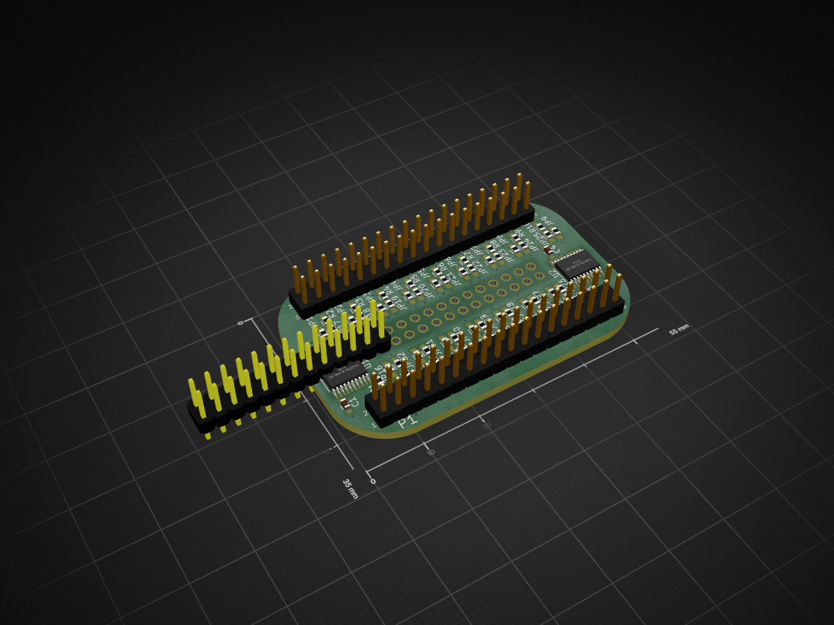
Cameo cape is an open-source printed circuit board by stepleton, from the stepleton/cameo repository on GitHub, published under the Unlicense licence. It is a 4-layer board of 55 × 35 mm with 58 parts on 101 nets, routed with 541 tracks and 88 vias.
Its parts include 17 resistors, 4 capacitors, 3 connectors and 2 ICs. It belongs with the interfaces and adapters boards of this library.
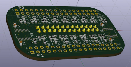
is a peripheral cape circuit board that allows the PocketBeagle single-board computer (which uses 3.3V digital signals) to interface with 5V digital logic. It is built around two Texas Instruments TXS0108EPWR or TXB0108PWR 8-bit bidirectional voltage level translator ICs. Sixteen digital I/O signal lines are available.
Cameo is optimised for applications that take advantage of the two PRU-ICSS real-time coprocessors built into the chip-like hybrid circuit that powers the PocketBeagle (a TI AM3358 SoC/Octavo OSD3358 SiP). The digital I/O lines that pass through Cameo include all fourteen logic lines the PRUs can access directly in either the input or output direction. The two remaining lines are one that PRU 0 can use for output only and one it can use for input only, the latter of which also happens to be the CLOCKIN line for the PRU's "parallel capture" input mode. Alternatively, all lines may be used bidirectionally via the AM3358's GPIO modules.
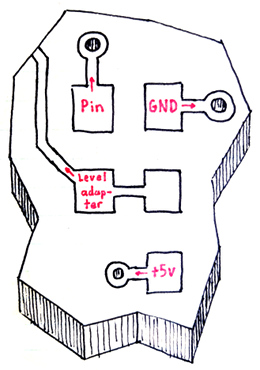
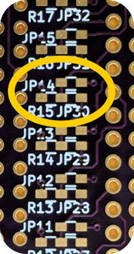
Cameo is "plugboard programmable": a pattern of jumper pads on the cape allow each signal line to be individually tied/pulled to GND or +5V, or to be terminated in a variety of ways, all through installation of appropriate 0603 surface-mount components (or, in a pinch, solder bridges or small fragments of wire). See the plugboard pad map for a diagram showing all of the "plugboard" pads.
Cameo and associated hardware designs, software materials, and other resources distributed alongside it are all made available for free with NO WARRANTY OF ANY KIND. Any system that interfaces with Cameo could suffer malfunction, data loss, physical damage, or other harms. Some of these effects could be permanent and/or unrepairable. If you're not prepared to risk these consequences, don't use Cameo.
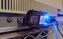 Aphid,
a hardware emulator for Apple parallel port hard drives.
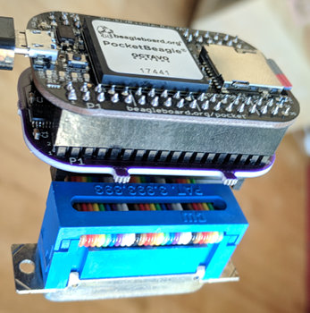
Cameo is designed to mount underneath the PocketBeagle, preserving easy access to the PocketBeagle's soft power button. The pin header for 5V digital I/O is mounted on the underside of Cameo. With a short ribbon cable like the one in the photo, the entire lightweight "stack" can dangle from a computer peripheral port, as long as clearances and the security/fastness of the connector allow.
To build a ready-to-use "stack" of your own from parts, you will need (prices for informational purposes only; many are likely out-of-date):
costing $52.15 in total. If you are willing to bond the PocketBeagle and Cameo together permanently, you can omit the 2x18 sockets and save a bit over $4.
Some applications may benefit from adapting the 26-pin header on the bottom of Cameo to a 25-pin DB-25 plug connector. To make this adaptor, you can use:
adding to an additional $4.19.
Cameo is not an ideal starter project for hobbyists new to soldering surface-mounted components; on the other hand, it doesn't have too many of them, and they're not very tightly packed. The following diagram shows the locations of essential SMD components on Cameo:
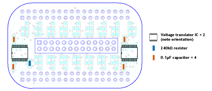
More SMD components will be required to set up the "plugboard" that connects PocketBeagle signal lines to pins on the 5V I/O header. The specific nature and configuration of these components are application-specific. See the introduction and the plugboard pad map for more details of the plugboard.
When assembling the Cameo board, it may be advisable to place the two voltage translator ICs first, followed by the discrete SMD components and then by the through-hole headers/connectors. Remember, Cameo expects to be slung underneath the PocketBeagle, so the 5V I/O header (centre) should emerge from the bottom of the board, while the headers (or sockets) for connecting to the PocketBeagle should emerge from the top.
To connect to Cameo, the PocketBeagle will need sockets (or headers) emerging from the bottom of its PCB. When mating Cameo to the PocketBeagle, be certain of the correct orientation: if Cameo is orientated as shown above, the USB connector on the PocketBeagle should be visible and pointing leftward.
Refer to online tutorials for making ribbon cable assemblies with IDC connectors (e.g.) to build an adaptor for the 5V I/O header. In general, it's best for the cable between the two connectors to be as short as possible.
The following pinout diagram represents Cameo's 26-pin 5V I/O header as viewed from the underside of the Cameo PCB, with the PocketBeagle's USB connector pointing upward.
| GPIO | PRU | PB pin | Name | I/O pin | I/O pin | Name | PB pin | PRU | GPIO | ||
|---|---|---|---|---|---|---|---|---|---|---|---|
| n/c | 1 | 2 | PEX3 | P1.35 | 1 ⇆ | 2.24 | |||||
| 1.10 | ⇆ 1 | P1.32 | PEX1 | 3 | 4 | \PSTRB | P2.9 | 0 ← | 0.15 | ||
| 1.11 | ⇆ 1 | P1.30 | PR/\W | 5 | 6 | \PBSY | P2.35 | 1 ⇆ | 2.22 | ||
| 2.25 | ⇆ 1 | P1.4 | PEX2 | 7 | 8 | \PCMD | P1.2 | 1 ⇆ | 2.23 | ||
| 3.14 | ⇆ 0 | P1.36 | PD0 | 9 | 10 | \PPARITY | P2.24 | 0 → | 1.12 | ||
| 3.15 | ⇆ 0 | P1.33 | PD1 | 11 | 12 | ⏚ | |||||
| n/c | 13 | 14 | ⏚ | ||||||||
| 3.16 | ⇆ 0 | P2.32 | PD2 | 15 | 16 | n/c | |||||
| ⏚ | 17 | 18 | PD3 | P2.30 | 0 ⇆ | 3.17 | |||||
| ⏚ | 19 | 20 | PD4 | P1.31 | 0 ⇆ | 3.18 | |||||
| 3.19 | ⇆ 0 | P2.34 | PD5 | 21 | 22 | ⏚ | |||||
| 3.20 | ⇆ 0 | P2.28 | PD6 | 23 | 24 | ⏚ | |||||
| 3.21 | ⇆ 0 | P1.29 | PD7 | 25 | 26 | ⏚ |
The names of the 5V I/O pins reflect one of the example applications and should be considered arbitrary. Pins marked n/c connect to nothing; pins marked ⏚ are tied to ground.
The "PB pin" column shows which PocketBeagle header pin connects to Cameo's 5V I/O header (through the 3.3V ⇆ 5V bidirectional voltage level translator ICs).
The "PRU" columns show which of the two PRU-ICSS real-time coprocessors in the AM3358 are connected to each pin. A ⇆ symbol means that the corresponding PocketBeagle pin can be configured either as an input to or an output of the PRU; the ← and → symbols mean that the pin can only be a PRU input or output respectively. Pins PD0-PD7 in particular map to PRU 0 GPIO bits 0-7.
The "GPIO" columns show how the pins correspond to I/O bits in the AM3358's GPIO modules ("3.21" means module 3, bit 21). All pins may be accessed in any direction through the GPIO subsystem.
For more detailed connectivity information, refer to the expansion header tables in the PocketBeagle reference manual.
Note finally that if an ordinary ribbon cable is used in an adaptor that connects the 5V I/O header to a DB-25 plug connector, the pin numbering patterns for both are different:
| DB-25 pin | 1 | 2 | 3 | 4 | 5 | 6 | 7 | 8 | 9 | 10 | 11 | 12 | 13 |
|---|---|---|---|---|---|---|---|---|---|---|---|---|---|
| Header pin | 1 | 3 | 5 | 7 | 9 | 11 | 13 | 15 | 17 | 19 | 21 | 23 | 25 |
| DB-25 pin | 14 | 15 | 16 | 17 | 18 | 19 | 20 | 21 | 22 | 23 | 24 | 25 |
|---|---|---|---|---|---|---|---|---|---|---|---|---|
| Header pin | 2 | 4 | 6 | 8 | 10 | 12 | 14 | 16 | 18 | 20 | 22 | 24 |
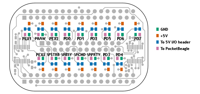
This diagram shows a top-side view of Cameo. (In this view, the through-holes for the 26-pin 5V I/O header (centre) are "flipped" about the header's long (horizontal) axis, since the pins emerge from the underside of the board.)
The installation of jumpers, resistors, or other 0603 surface mount components on each set of five pads shaped like ⠾, ⠻, or ⠷ determines whether and how the labelled pin connects (through the voltage translator ICs) to the PocketBeagle.
Cameo was designed with KiCad 4. Project files and derived products (Gerber files, etc.) are kept in the hardware subdirectory.
To the fullest extent possible, Cameo is released into the public domain. Nobody owns Cameo.
It would not have been possible for me to design Cameo without the help of the following people and resources:
-- Tom Stepleton, 11 August 2018, London
| Qty | Value | Footprint | References |
|---|---|---|---|
| 16 | Jumper_NC_Small | Resistors_SMD:R_0603_HandSoldering | JP3, JP4, JP5, JP6, JP7, JP8, JP9, JP10, JP11, JP12, JP13, JP14, JP15, JP17, JP18, JP32 |
| 16 | Jumper_NO_Small | Resistors_SMD:R_0603_HandSoldering | JP1, JP2, JP16, JP19, JP20, JP21, JP22, JP23, JP24, JP25, JP26, JP27, JP28, JP29, JP30, JP31 |
| 16 | R_Small | Resistors_SMD:R_0603_HandSoldering | R2, R3, R4, R5, R6, R7, R8, R9, R10, R11, R12, R13, R14, R15, R16, R17 |
| 4 | 0.1 | Capacitors_SMD:C_0603_HandSoldering | C1, C2, C3, C4 |
| 2 | TXS0108E_PW_20 | footprints.pretty:TXS0108EPWR | U1, U2 |
| 2 | ~ | PocketBeagle.pretty:TH-2X18-(35MIL-DIA)-W_O-SILK | P1, P2 |
| 1 | 10K | Resistors_SMD:R_0603_HandSoldering | R1 |
| 1 | CONN_02X13 | Pin_Headers:Pin_Header_Straight_2x13 | P3 |
It measures 55 × 35 mm and has 4 copper layers, 1.6 mm thick.
58 parts. The full list of its parts is on this page, with links to each part's symbol and footprint where PCBKit's library has them.
From the stepleton/cameo repository on GitHub, at the commit this page was made from: the board is hardware/cameo_cape/cameo_cape.kicad_pcb. PCBKit opens the board in the browser, with nothing to install.
Its repository publishes it under the Unlicense licence: you may reuse it on that licence's terms (keep the author's notice, and for a copyleft licence share your changes alike).
Seeed-Studio/OSHW-reCamera-Series
reCamera is a series of open-source AI cameras.


Bellafaire/ESP32-Smart-Watch
An open source smartwatch based on the ESP32 compatible with the Arduino IDE.

murexrobotics/electrical
Highly integrated electronics design and printed circuit boards (PCBs) for the MATE ROV Competition. Attempt the impossible.

will127534/Miniature-CM4-Cluster
A dense cluster for four Raspberry Pi Compute Module 4


ricardoquesada/unijoysticle2
Bluetooth gamepad support for the Commodore 64 / Atari / Amiga, etc.
