
2 layers33.7 × 97.8 mm
HAN ESP TSS721
UtilitechAS/amsreader-firmware
ESP8266 and ESP32 compatible firmware to read, interpret and publish data to MQTT from smart electrical meters, both DLMS and DSMR is supported
29 parts470

 stephenjdc/TapeDispenser21
An open-source recreation of the "Welcome to Kilnettle" tape dispenser from Father Ted.
TapeDispenser is an open-source printed circuit board by stephenjdc, from the stephenjdc/TapeDispenser repository on GitHub. It is a 2-layer board of 50 × 30 mm with 15 parts on 25 nets, routed with 61 tracks and 0 vias.
It is built around the ESP-12E. Its parts include 5 resistors, 3 diodes, 2 connectors, 1 IC and 1 transistor. It belongs with the ESP8266 boards of this library.
Blog post: https://stephencoyle.net/kilnettle
If you'd like to build your own tape dispenser, which tells you how much you've used, and blesses you afterwards, you have two choices.
Please note that, while the dispenser does aim to fairly accurate, it's not perfectly accurate as it doesn't adjust for the amount of tape used. In the code I've just split the error, so it will tend to overshoot the measurement when a roll is full, and undershoot a bit when it's empty. Given we're only dealing with one-inch resolution, I feel like it's probably fine. You can tweak the code if you want to try and improve on this. There's also is a no-code way to tweak it, detailed below.
Feel free to make/reuse/modify this project for personal use. In the unlikely event that you're planning to spin up a large-scale production line to make thousands of these, I'd really recommend doing a few more revisions on the code and the models. In which case, I'm available at a very reasonable rate.
There are included KiCAD files which you can use to create a PCB for this, but you could also use point-to-point soldering or stripboard (see below).
| PCB Label | Component | Description |
|---|---|---|
R1 | 1K resistor | |
R2 | 220R resistor | |
R3 | 1K resistor | |
R4 | 10K resistor | |
R5 | 10K resistor | |
D1 | Photodiode | Small black LED |
D2 | IR LED | Small clear LED |
D3 | Indicator LED | Red LED |
LS1 | Speaker | |
Q1 | 2N3904 Transistor | |
U1 | ESP8266 | |
J1 | GND | |
J2 | +3V |
I'm gonna keep these fairly sparse, and following what I did. But there's no right way to do it. In the very unlikely event that you actually want to make one yourself, and run into trouble, feel free to message me with any questions. The video version may also be more useful!
If you're not able to make a PCB, you could use a D1 Mini and some stripboard. See an example layout below that uses an MC01009 board. It uses uses pin headers so that each part can be connected using female jumper wires. Use a rotary tool cutting wheel to trim the board down so it can fit just behind the speaker.
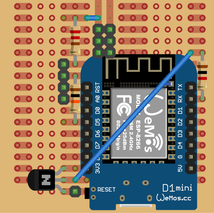
There are some notable differences when using the D1 mini board:
board = d1_mini in platformio.ini#define ESP8266_Variant in src/main.cppYou can easily test it without a spool, by waving your finger around in the spool cavity, making sure you block the IR beam a few times. ↩
| Qty | Value | Footprint | References |
|---|---|---|---|
| 2 | 10K | Resistor_THT:R_Axial_DIN0207_L6.3mm_D2.5mm_P10.16mm_Horizontal | R4, R5 |
| 2 | 1K | Resistor_THT:R_Axial_DIN0207_L6.3mm_D2.5mm_P10.16mm_Horizontal | R1, R3 |
| 2 | MountingHole | MountingHole:MountingHole_2.2mm_M2 | H1, H2 |
| 1 | +3V0 | Connector_Wire:SolderWire-0.5sqmm_1x01_D0.9mm_OD2.1mm | J2 |
| 1 | 220R | Resistor_THT:R_Axial_DIN0207_L6.3mm_D2.5mm_P10.16mm_Horizontal | R2 |
| 1 | 2N3904 | Package_TO_SOT_THT:TO-92_Inline | Q1 |
| 1 | ESP-12E | RF_Module:ESP-12E | U1 |
| 1 | GND | Connector_Wire:SolderWire-0.5sqmm_1x01_D0.9mm_OD2.1mm | J1 |
| 1 | IR LED | Connector_Wire:SolderWire-0.5sqmm_1x02_P4.6mm_D0.9mm_OD2.1mm | D2 |
| 1 | IR Photodiode | Connector_Wire:SolderWire-0.5sqmm_1x02_P4.6mm_D0.9mm_OD2.1mm | D1 |
| 1 | LED | Connector_Wire:SolderWire-0.5sqmm_1x02_P4.6mm_D0.9mm_OD2.1mm | D3 |
| 1 | Speaker | Connector_Wire:SolderWire-0.5sqmm_1x02_P4.6mm_D0.9mm_OD2.1mm | LS1 |
It measures 50 × 30 mm and has 2 copper layers, 1.6 mm thick.
15 parts, built around the ESP-12E. The full list of its parts is on this page, with links to each part's symbol and footprint where PCBKit's library has them.
From the stephenjdc/TapeDispenser repository on GitHub, at the commit this page was made from: the board is pcb/TapeDispenser.kicad_pcb and its schematic pcb/TapeDispenser.kicad_sch. PCBKit opens the board in the browser, with nothing to install.
Its repository states no licence, so its author keeps all rights: ask stephenjdc before reusing the design.
UtilitechAS/amsreader-firmware
ESP8266 and ESP32 compatible firmware to read, interpret and publish data to MQTT from smart electrical meters, both DLMS and DSMR is supported


skorokithakis/tiny-ESP8266-breakout
A very small and basic ESP8266 breakout board

mcbittech/souliss-smart-thermostat-WiFi
ESP8266 WiFi Smart Thermostat based on Souliss IoT Framework

girst/hardpass-passwordmanager-mirror-of-git.gir.st
https://git.gir.st/hardpass.git - Seldomly Updated Mirror: Hardpass is a Raspberry Pi Zero based hardware password manager, using passwordstore.org.

MakerMeik/Window-Sensor
Here you will find all the files you need to build an ESP8266-based window sensor whose battery will last for several years. Have a look at my video on Youtube: https://youtu.be/vxbuO1zWo3w

