2 layers158 × 11 mm
Daylight Matchstick
VoronDesign/Voron-Hardware
Cool Hardware designed by the Voron Design group
22 parts1.1kGPL-3.0

 steam228/GROUU3
Open Hardware and Software Project
Layouts is an open-source printed circuit board by steam228, from the steam228/GROUU repository on GitHub. It is a 2-layer board of 52.8 × 45.7 mm with 22 parts on 24 nets, routed with 253 tracks and 15 vias.
Its parts include 9 resistors, 6 ICs, 3 transistors, 3 connectors and 1 capacitor. It belongs with the ESP8266 boards of this library.

GROUU enables the implementation of Precision Agriculture / Automation in the context of personal or small scale agricultures. At the moment, the development goals for GROUU V2 is to implement a local/edge server based on a raspberry pi or other linux mini computer, a sensor node template with wifi communication and other with LoraWAN communication. The same for two actuator templates. when this basic infrastructure is designed we will apply it to personal contexts in order to test it. This process will generate new repositores. This Git repository also archives the personal development and learning process behind the project and research done throught it.
Let us know if you want to collaborate
A well-water-quality LoRaWAN sensor node (XIAO ESP32-S3 + Wio-SX1262): reads water temperature / TDS / turbidity / pH, encodes them as CayenneLPP, and uplinks to The Things Network (EU868, OTAA) while deep-sleeping between readings. On a Raspberry Pi the data flows TTN → Node-RED → InfluxDB 2 → Grafana, and a small public dashboard renders it live.
📁 /ARDUINO/GROUU_V3/ · 📊 live dashboard: https://grouuwell01.hacktoimprove.com
Full docs — hardware, firmware bring-up, calibration, data pipeline, the web dashboard, and the dedicated atopile PCB — are in ARDUINO/GROUU_V3/README.md.
GROUU V2 Sensor Modules Configuration
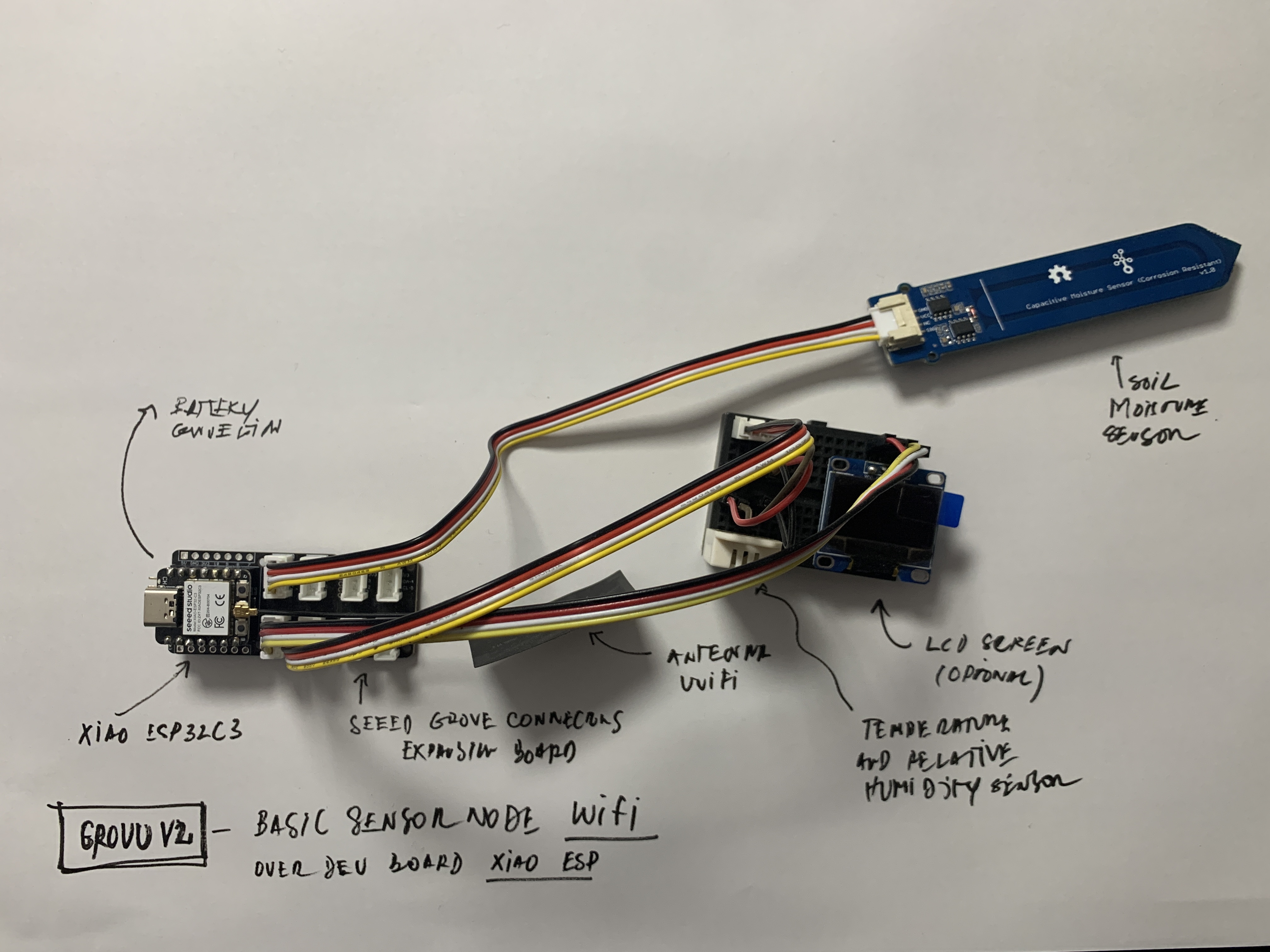
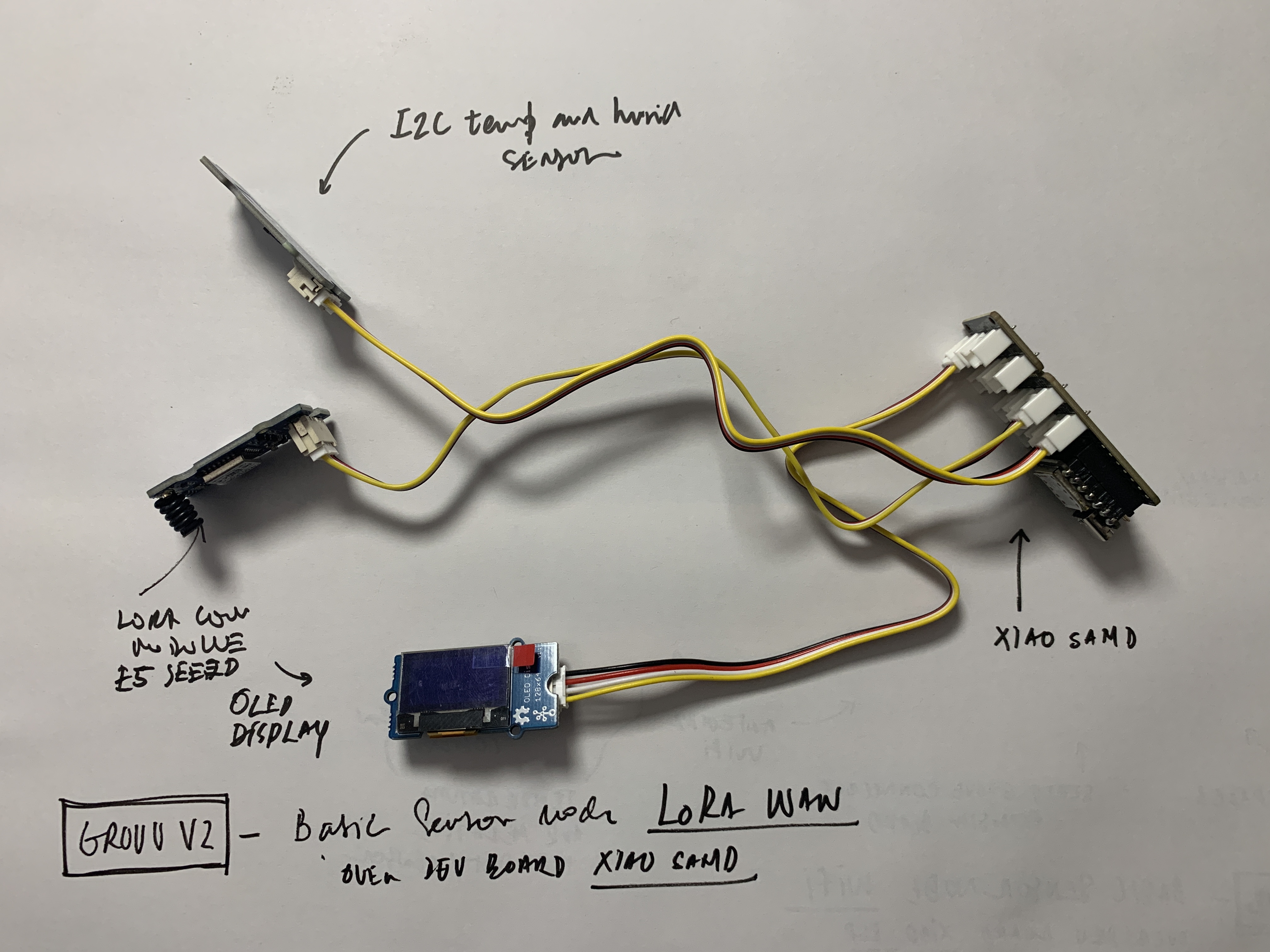
GROUU V2 Sensor Actuator Configuration
GROUU Server V2 Configuration(GROUU Stack V1)
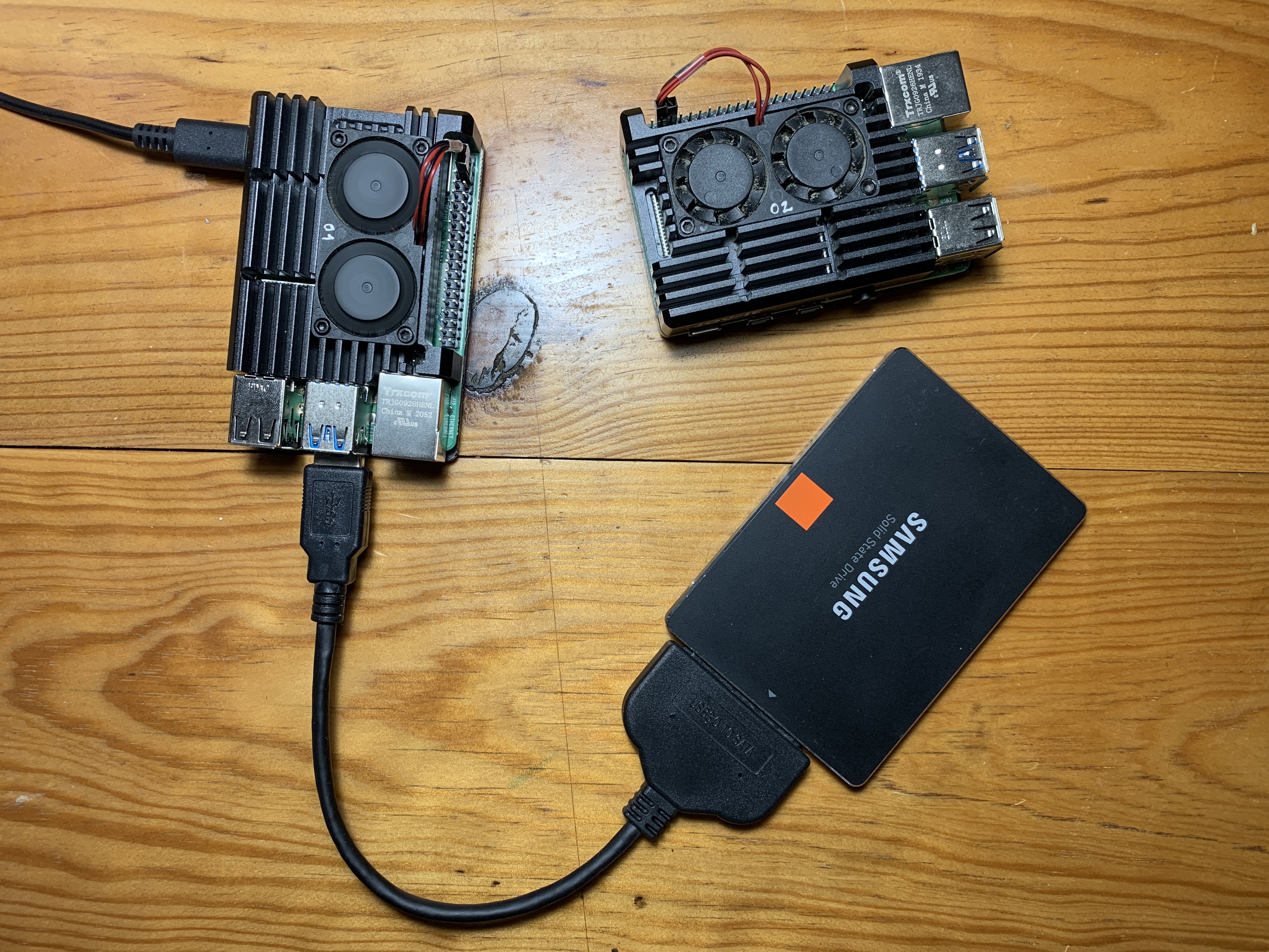
The GROUU Stack V1 (part of GROUU V2) provides an advanced foundation for your open-source IoT farming project:
This guide will help you set up the GROUU Stack V1, an open-source IoT solution for personal and small-scale farming.
First, we need to install Docker on your Linux system:
# Update and upgrade the system
sudo apt update && sudo apt upgrade -y

# Install required packages
sudo apt install -y apt-transport-https ca-certificates curl gnupg lsb-release

# Add Docker's official GPG key and set up the repository
curl -fsSL https://get.docker.com -o get-docker.sh
sudo sh get-docker.sh

# Add your user to the docker group
sudo usermod -aG docker $USER

# Enable Docker to start on boot
sudo systemctl enable docker
Log out and log back in for the group changes to take effect.
Now, let's install Portainer:
# Create volume for Portainer
docker volume create portainer_data

# Install Portainer CE
docker run -d -p 8000:8000 -p 9000:9000 --name=portainer --restart=always \
  -v /var/run/docker.sock:/var/run/docker.sock \
  -v portainer_data:/data \
portainer/portainer-ceOpen a web browser and navigate to http://your-server-ip:9000. You'll be prompted to create an admin user.
version: '3'

services:
  mosquitto:
    image: eclipse-mosquitto:latest
    ports:
      - "1883:1883"
    volumes:
      - mosquitto-config:/mosquitto/config
      - mosquitto-data:/mosquitto/data
      - mosquitto-log:/mosquitto/log
    restart: always

  nodered:
    image: nodered/node-red:latest
    ports:
      - "1880:1880"
    volumes:
      - nodered-data:/data
    restart: always

  influxdb:
    image: influxdb:latest
ports:After deploying the GROUU Stack V1, you can access its components:
http://your-server-ip:1880http://your-server-ip:8086http://your-server-ip:3000your-server-ip:1883Remember to replace your-server-ip with your actual server IP address.
Congratulations! You now have the GROUU Stack V1 up and running for your personal or small-scale farming IoT project.
If you prefer not to use the stack configuration, you can follow these steps for manual installation:
Follow the Docker installation steps from the stack installation guide above.
# Create volume for Portainer
docker volume create portainer_data

# Install Portainer CE
docker run -d -p 8000:8000 -p 9000:9000 --name=portainer --restart=always -v /var/run/docker.sock:/var/run/docker.sock -v portainer_data:/data portainer/portainer-ce

# Install Portainer Agent
docker run -d -p 9001:9001 --name portainer_agent --restart=always -v /var/run/docker.sock:/var/run/docker.sock -v /var/lib/docker/volumes:/var/lib/docker/volumes portainer/agentAccess Portainer web interface at http://your-server-ip:9000 and follow these steps for each container:
Follow the post-deployment steps and security considerations from the stack installation guide above.
Under development - design (boards, enclosures), firmware (Arduino)
const String Instalation = "myFarm"; //Where is it?
const String IDCODE = "1"; //number your probe
const String TYPE = "SoilProbe"; //choose type
const String Host = "Grouu" + Instalation + TYPE + IDCODE; //just change if it is not grouu and you're adapting the code for something else
const char * OTA_PASSWORD  = "yourpasswordhere";
will allow you to set a hostname (Host) - These are the only parameters you should have to change before injecting the firmware on your board (we should work on an even simpler method);
This hostname (const String Host):
HostName/Sensor/Moist1);There shouldn't be a limit for the amount of modules developed nor used. The scale and context should dictate these options.
All Explorations, independently from the context or scale should be considered valid data generators;
It is permanent, develop whatever you want whenever you want!
Right now we are using a standard Raspberry case.
Configuring the Pi: Tutorial Link
Accessing through ssh on mac or linux terminal: Tutorial Link
Upgrade Node-Red and Node.js
sudo apt-get update
sudo apt-get upgrade
bash <(curl -sL https://raw.githubusercontent.com/node-red/raspbian-deb-package/master/resources/update-nodejs-and-nodered)
sudo systemctl enable nodered.service
Connect to Raspberry Pi Node-red console through your browser by accessing http://"raspipaddress":1880
Install Mosquitto MQTT broker
sudo apt-get install mosquittoSome instructions on how to test here: Instructables Tutorial
Developed at the Habibi Works (Ioannina, Greece) CultiMake Workshop - P2PLab
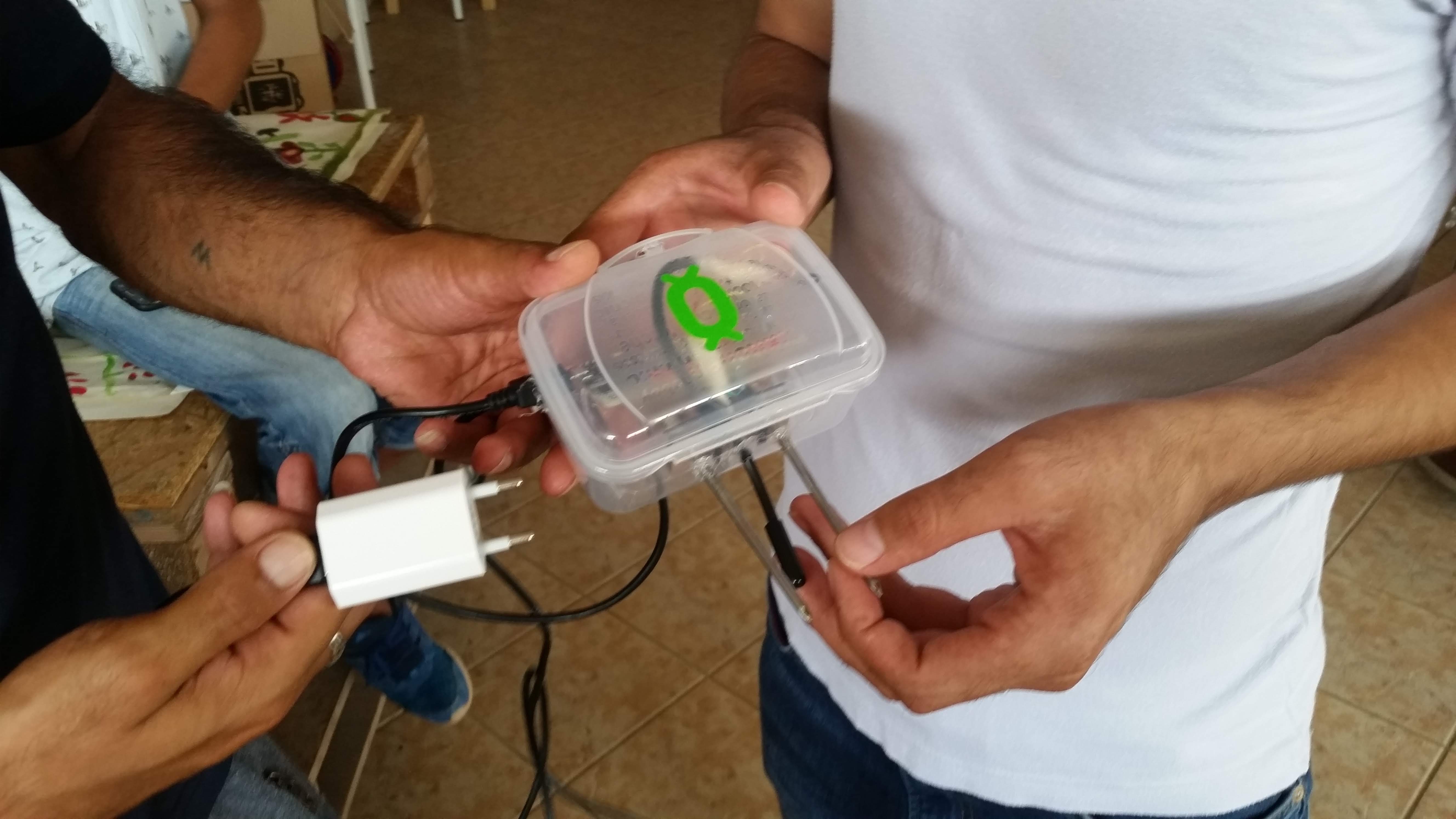
This board includes:
Arduino IDE Firmware: /ARDUINO/habibiWorksJuly2018-WS/grouu-irr
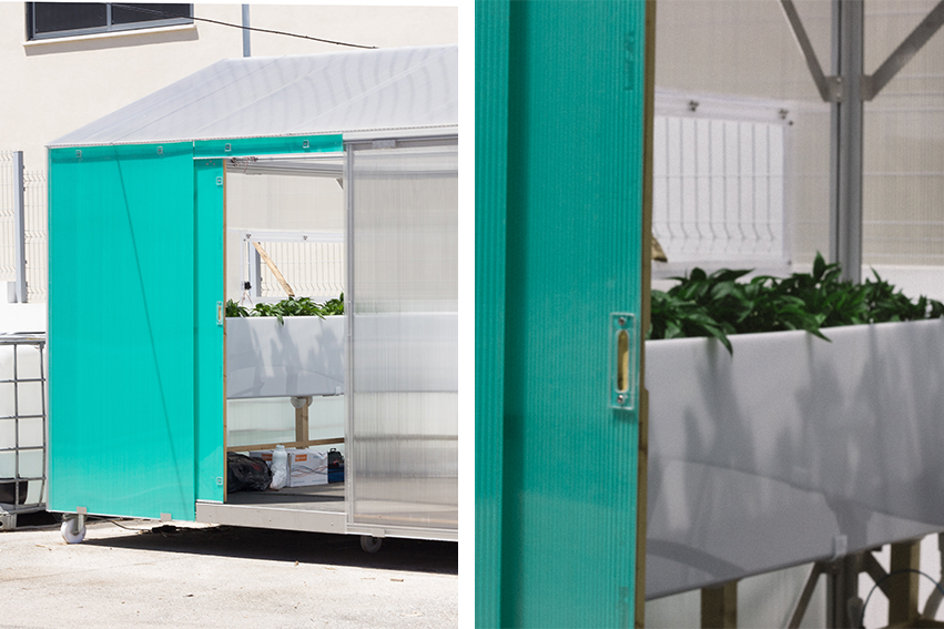
Arduino Yun code: /ARCHIVE/arduino/GROUU_GREENHOUSE_0/
| Qty | Value | Footprint | References |
|---|---|---|---|
| 4 | Cixi_Kefa_Elec_KF301_5_0_3P:CONN-TH_3P-P5.00_KF301-5.0-3P | U2, U3, U4, U5 | |
| 3 | 4.7kΩ ±1% | UNI_ROYAL_1206W4F4701T5E:R1206 | R1, R6, R7 |
| 2 | XKB_Connectivity_X2011WV_04A_N0SN:CONN-TH_4P-P2.00_L5.1-W10.0 | CN1, CN2 | |
| 2 | Alpha___Omega_Semicon_AO3401A:SOT-23_L2.9-W1.3-P1.90-LS2.4-BR | Q2, Q3 | |
| 2 | 100kΩ ±5% | FOJAN_FRC1206J104_TS:R1206 | R2, R3 |
| 2 | 10kΩ ±1% | UNI_ROYAL_1206W4F1002T5E:R1206 | R5, R9 |
| 1 | Texas_Instruments_ADS1115IDGSR:MSOP-10_L3.0-W3.0-P0.50-LS5.0-BL | U1 | |
| 1 | XIAO_ESP32S3:XIAO-ESP32-S3-SMD_PAD | U6 | |
| 1 | PUOLOP_2N7002_SOT23:SOT-23_L2.9-W1.3-P1.90-LS2.4-BR | Q1 | |
| 1 | JST_Sales_America_B2B_PH_K_S_LF__SN:CONN-TH_B2B-PH-K-S | CN3 | |
| 1 | 100nF ±10% | Samsung_Electro_Mechanics_CL31B104KBCNNNC:C1206 | C1 |
| 1 | 18kΩ ±1% | FOJAN_FRC1206F1802TS:R1206 | R4 |
| 1 | 6.8kΩ ±1% | UNI_ROYAL_1206W4F6801T5E:R1206 | R8 |
It measures 52.8 × 45.7 mm and has 2 copper layers, 1.6 mm thick.
22 parts. The full list of its parts is on this page, with links to each part's symbol and footprint where PCBKit's library has them.
From the steam228/GROUU repository on GitHub, at the commit this page was made from: the board is ARDUINO/GROUU_V3/hardware/well-bouy01/layouts/default/default.kicad_pcb. PCBKit opens the board in the browser, with nothing to install.
Its repository states no licence, so its author keeps all rights: ask steam228 before reusing the design.
VoronDesign/Voron-Hardware
Cool Hardware designed by the Voron Design group

hoglet67/RGBtoHDMI
Bare-metal Raspberry Pi project that provides pixel-perfect sampling of Retro Computer RGB/YUV video and conversion to HDMI

hackclub/OnBoard
💡 Join 1,000 teenagers and make your first PCB with a $100 grant!

abhishek-kakkar/BeagleLogic
A Software Suite that implements a logic analyzer with the PRU on the BeagleBone / BeagleBone Black.

Chrismettal/flipper-zero-backpacks
Backpack-style addon boards for the Flipper Zero!


CRImier/MyKiCad
My KiCad boards. Can't be bothered uploading individually anymore, so here you go.