

2 layers167 × 52 mm
In-2-nixie
mistic100/Nixie-Clock-IN2
Check out my other projects: - Nixie Clock IN14 - Nixie Clock IN12 - IV-27 VFD Clock
34 parts10

 starbuck93/hue-cube
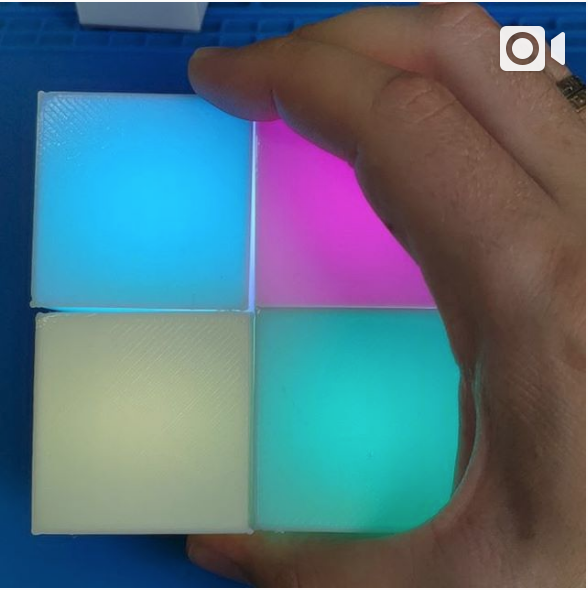
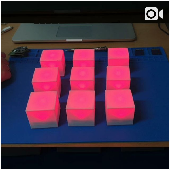
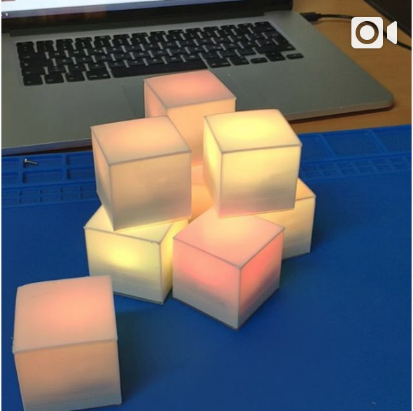
The HueCube is a small colorful, programmable cube, measuring 46x46x46mm.
Hue cube v3 is an open-source printed circuit board by starbuck93, from the starbuck93/hue-cube repository on GitHub. It is a 2-layer board of 39.4 × 40.6 mm with 15 parts on 11 nets, routed with 96 tracks and 15 vias.
It is built around the BME280 and WS2812B. Its parts include 5 ICs, 3 capacitors, 3 diodes, 1 connector and 1 switch.
The HueCube is a small colorful, programmable cube measuring 46x46x46mm. You can play around with the example code using the Arduino IDE, and change it's behavior. By reading data from the embedded sensors, you can let the colors change by temperature, height, angle, tapping, tilting, dropping or humidity. See the following videos for a few examples:
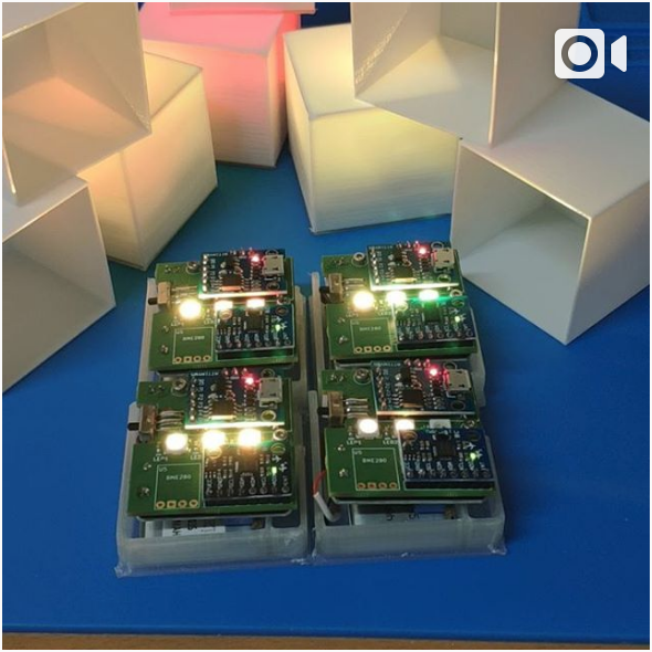
To assemble the board you need to be able to solder SMD components (0603) and a few pins. I am using this and this.


/light_ws2812_Arduino/ folder and place it into Arduino/libraries/. I chose this library, due to the small flash size of the attiny85.The HueCube is made of small, electronic modules that are soldered onto a PCB. You can order the PCB directly from AISLER, or use the KiCad project files form this repository to modify it. Currently, there are two design variant.
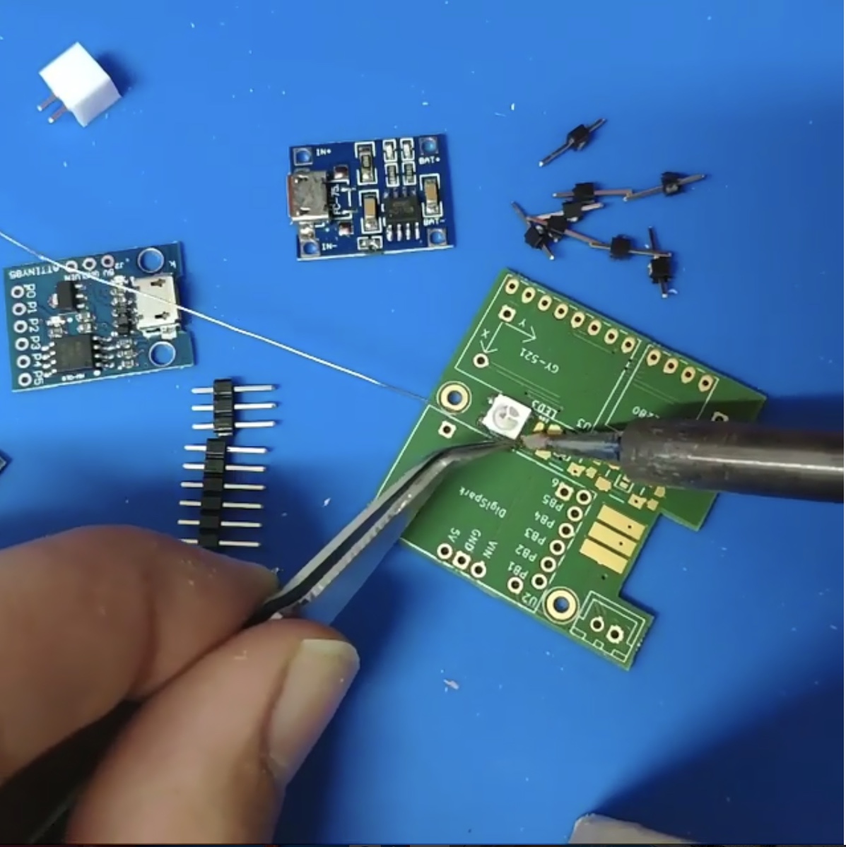
BlenderModel/hc-v3-usb-base.stl and 1x BlenderModel/hc-v3-usb-cube.stlBlenderModel/hc-v3-lipo-base.stl and 1x BlenderModel/hc-v3-lipo-cube.stlFirst, solder the WS2812B to the PCB, note the corner with the triangle is GND, so this needs to be aligned to the bottom right pad. See the video for detais:
Video:
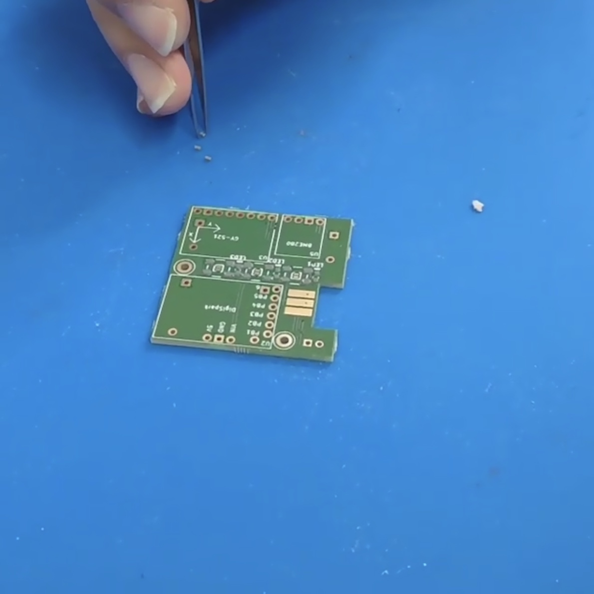
If you have a hot airstation and liquid solder, it is a lot easier to solder the SMD components:
Video:
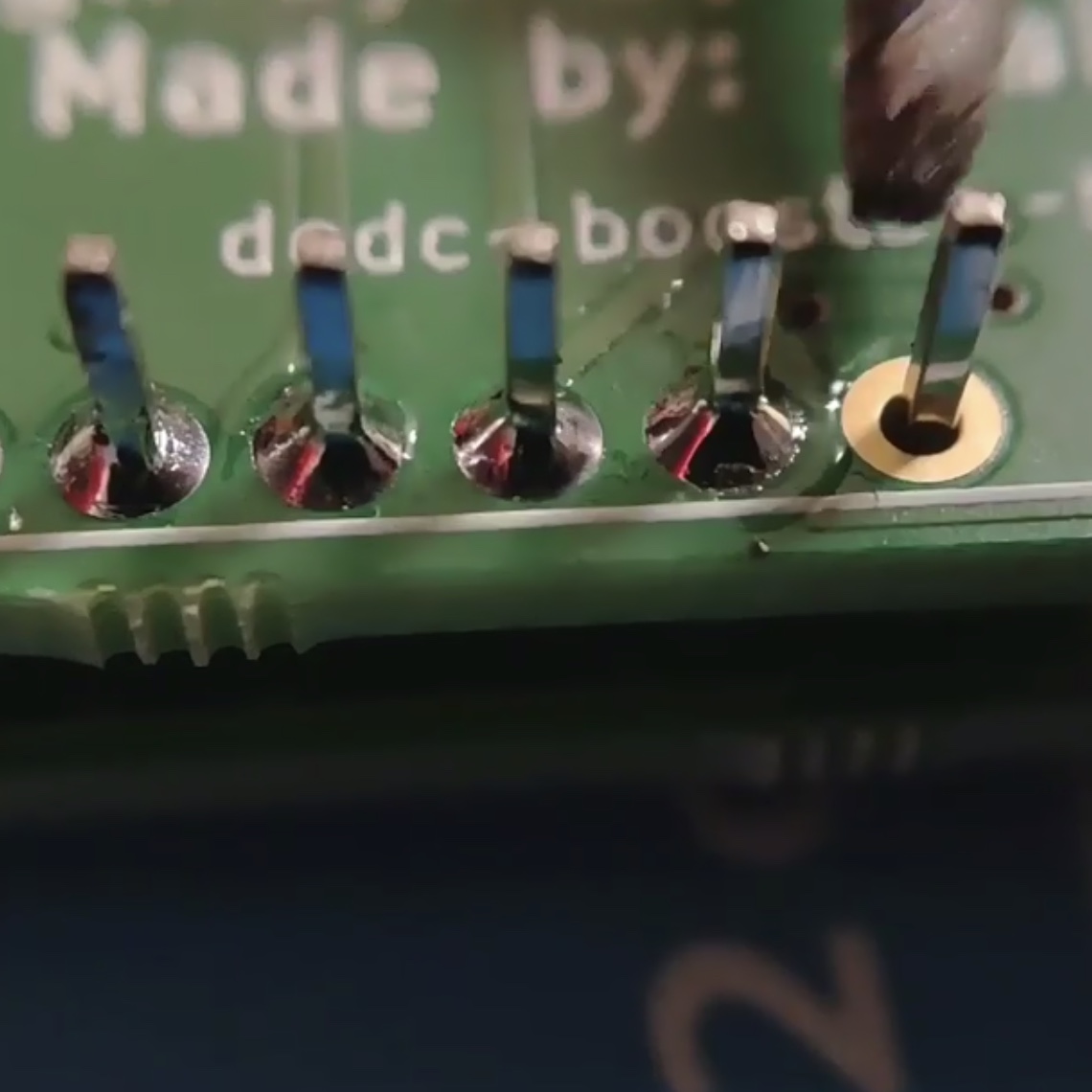
After the LEDs and capacitors, you will need to solder the pins. Important: You need to know in advance if you want to build the LiPo version or not, otherwise you will not be able to add the respective pins for the DCDC booster and the LiPo charger module.
Video:
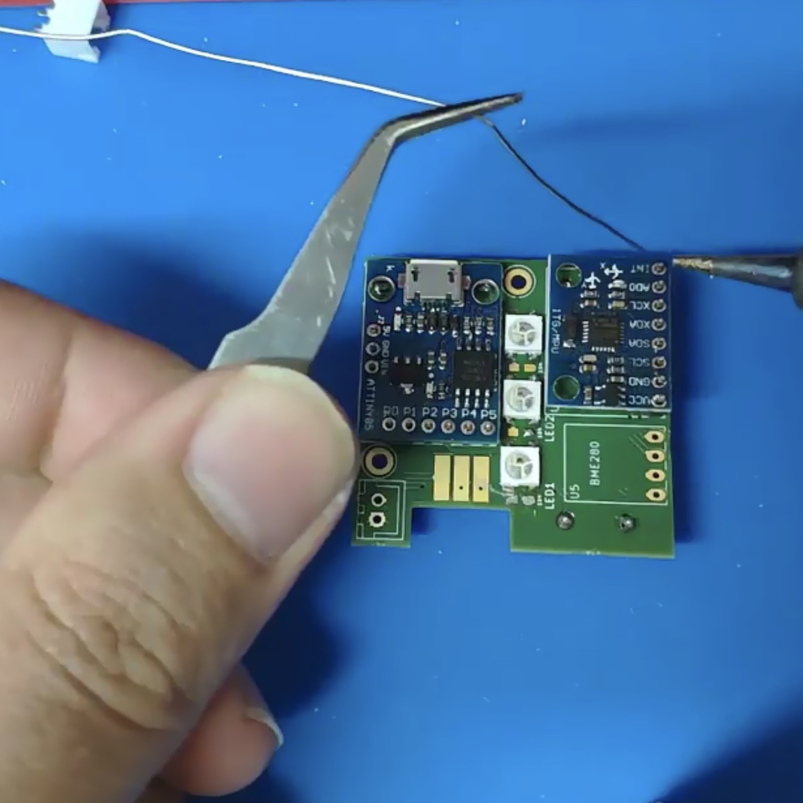
The USB version only requires soldering the top parts
Video:
Note, make sure you have the pins in place. Set the DCDC booster to 5V before soldering and replace the PROG resistor with a 10k resistor to make sure you only have small charging current of about 120mA.
Video:
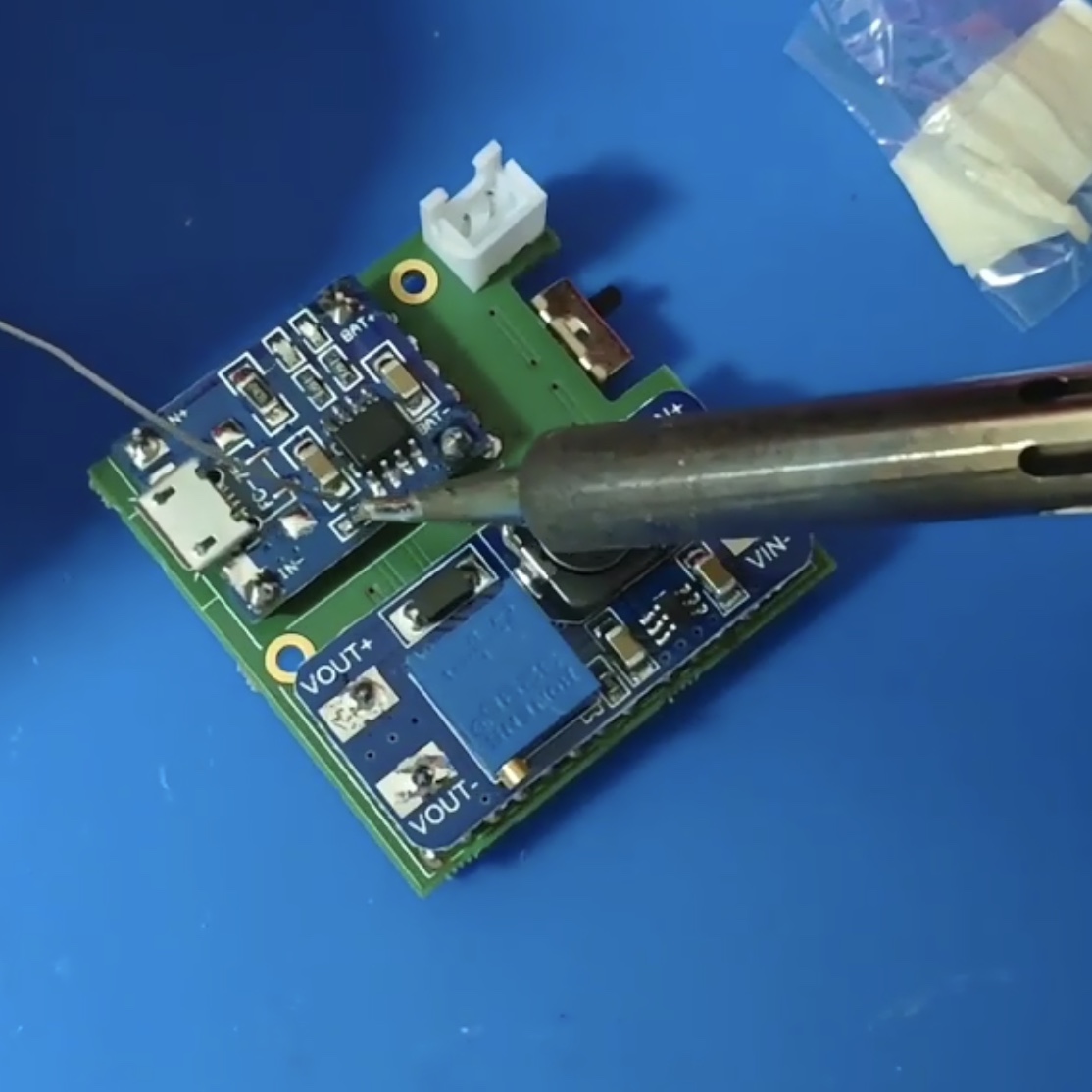
I think you will figure these out on your own. The square pin hole (PCB rev.8) is GND (black cable), the other 3.7V (red cable). Solder the connector facing to the bottom, i.e. not on the side of the LEDs. The switch selects whether the LiPo charger is connected (=OFF or Charging) or the DCDC booster is conencted (=ON). Never connect the USB while the huecube is on. I have done it and nothing happened. But it is not designed to work this way.
TODO 😅
TODO
See the respective subfolders for their LICENSE.
| Qty | Value | Footprint | References |
|---|---|---|---|
| 3 | 104 | Lib_Uvwxy:C_0603_HandSoldering_narrow | C1, C2, C3 |
| 3 | WS2812B | Lib_Uvwxy:WS2812B_data-bridgeable | LED1, LED2, LED3 |
| 1 | 3.7V LiPo | Connectors_JST:JST_XH_B02B-XH-A_02x2.50mm_Straight | J1 |
| 1 | BME280 | Lib_Uvwxy:BME280 | U5 |
| 1 | DigiSpark | Lib_Uvwxy:DigiSpark | U2 |
| 1 | GY-521 | Lib_Uvwxy:GY-521 | U3 |
| 1 | SW_DPDT_x2 | Lib_Uvwxy:flat-switch-2.54mm-smd | SW1 |
| 1 | dcdc-booster-board | Lib_Uvwxy:dcdc-booster-board | U4 |
| 1 | lipo-charger-module | Lib_Uvwxy:lipo-charger-board | U1 |
The 13 most common of 15 parts.
It measures 39.4 × 40.6 mm and has 2 copper layers, 1.6 mm thick.
15 parts, built around the BME280 and WS2812B. The full list of its parts is on this page, with links to each part's symbol and footprint where PCBKit's library has them.
From the starbuck93/hue-cube repository on GitHub, at the commit this page was made from: the board is KicadProject/hue-cube-v3/hue-cube-v3.kicad_pcb. PCBKit opens the board in the browser, with nothing to install.
Its repository states no licence, so its author keeps all rights: ask starbuck93 before reusing the design.
mistic100/Nixie-Clock-IN2
Check out my other projects: - Nixie Clock IN14 - Nixie Clock IN12 - IV-27 VFD Clock

heckler/esphome-device-configs
Configuration definitions for local ESPHome files

CommanderRedYT/ws2812-clock
A simple pcb clock using ws2812 in 7-segment form


beaked99/air-scales
2025-11-20. Updated all the footprints and symbols to their proper layouts. no more fkn errors. Hallefuckinglujah. Fucked up with LM74610 not using the right footprint. minor fix. 2025-11-16.

dharaneesh-m-oss/lorawatch_pcb
Compact LoRa-based Wearable IoT PCB using ESP32 with GPS, MPU6050, BME280, USB-C charging, and battery management designed in KiCad.

ficosta/Guardian-Sense
Guardian-Sense is a versatile hardware project based on the ESP32-S3, designed to monitor environmental conditions and provide real-time data to Zabbix.