2 layers19 × 76 mm
Sub
google/mozc-devices
Circuit diagrams and firmware source code for Gboard DIY keyboards
15 parts3kApache-2.0
 StaphSynth/input-selector
4-way stereo input selector PCB design
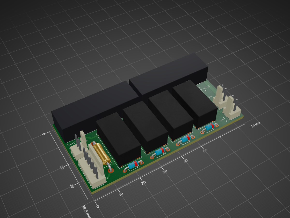
Input board is an open-source printed circuit board by StaphSynth, from the StaphSynth/input-selector repository on GitHub. It is a 2-layer board of 74 × 38.5 mm with 15 parts on 26 nets, routed with 79 tracks and 0 vias.
Its parts include 6 connectors, 4 diodes, 4 switches and 1 resistor.
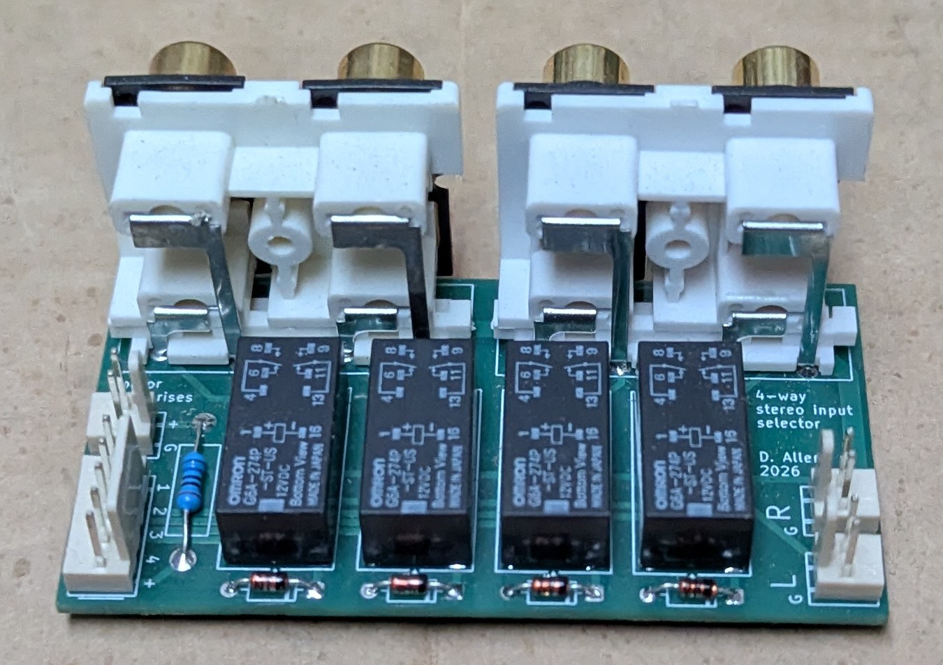
This is a 4-way stereo RCA input selector PCB design I made for some personal electronics projects. This board design is free to use for anyone who wants it. It was designed using KiCad and the project files are included in the KiCad/ folder.
If you just want to have the board manufactured, you can use the pre-made gerber files in the gerbers/ folder and send them to your favourite fab house.
The board has two input pin-headers on the left, and left and right audio channel output pin headers on the right.
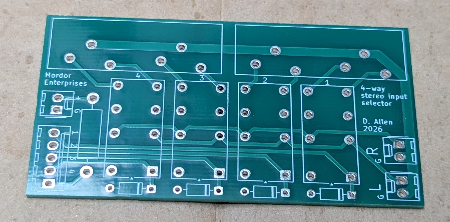
The top left header is for relay power and ground. This passes through resistor R1 before appearing on the second header. I've intentially not specified a value for this resistor as it is meant to drop your rail voltage to whatever coil voltage you need for your relays. You can replace it with a wire link if no dropper-resistor is required.
The second header goes to your switching solution, whether that be a manual rotary switch or electronic equivalent. The switch should connect the positive rail to the relay of your choice, which will then close and connect its RCA sockets to the output pin headers on the right-hand side of the board.
The board requires full-current drive for the relays. This board is not suitable for using low-level switching signals to drive the relays. I intentionally did not include space for a transistor to drive each relay coil to save space (and because it was not required in my projects). There's nothing stopping you from doing this yourself elsewhere in your project, just be aware of this limitation.
The relay power ground and analogue signal grounds not connected on the board. You can do this yourself if required by simply soldering a wire link between an RCA ground pin and the board ground plane, but I opted to keep them separate for maximum flexibility.
The board was designed for G6A relays, but any small signal relay with an equivalent footprint can probably be substituted. Note that these are often polarised to reduce drive current, so take care to ensure correct coil polarity.
The board was designed to accept PHS-14B-style PCB-mount RCA sockets.
None
| Qty | Value | Footprint | References |
|---|---|---|---|
| 4 | 1N4148 | Diode_THT:D_DO-35_SOD27_P7.62mm_Horizontal | D1, D2, D3, D4 |
| 4 | G6A | Relay_THT:Relay_DPDT_Omron_G6A | K1, K2, K3, K4 |
| 3 | Conn_01x02_Socket | Connector_Molex:Molex_KK-254_AE-6410-02A_1x02_P2.54mm_Vertical | J3, J4, J7 |
| 2 | ~ | Library:RCA_4 | J1, J2 |
| 1 | Conn_01x05_Socket | Connector_Molex:Molex_KK-254_AE-6410-05A_1x05_P2.54mm_Vertical | J6 |
| 1 | R | Resistor_THT:R_Axial_DIN0411_L9.9mm_D3.6mm_P15.24mm_Horizontal | R1 |
It measures 74 × 38.5 mm and has 2 copper layers, 1.6 mm thick.
15 parts. The full list of its parts is on this page, with links to each part's symbol and footprint where PCBKit's library has them.
From the StaphSynth/input-selector repository on GitHub, at the commit this page was made from: the board is KiCad/input-board.kicad_pcb and its schematic KiCad/input-board.kicad_sch. PCBKit opens the board in the browser, with nothing to install.
Its repository states no licence, so its author keeps all rights: ask StaphSynth before reusing the design.
google/mozc-devices
Circuit diagrams and firmware source code for Gboard DIY keyboards

hoglet67/RGBtoHDMI
Bare-metal Raspberry Pi project that provides pixel-perfect sampling of Retro Computer RGB/YUV video and conversion to HDMI

mntmn/amiga2000-gfxcard
MNT VA2000, an Open Source Amiga 2/3/4000 Graphics Card (Zorro II/III), written in Verilog

hackclub/OnBoard
💡 Join 1,000 teenagers and make your first PCB with a $100 grant!

kenp-io/not-for-airpods-repairs
The content of this repository is licensed under the WTFPL License. Please have a close look at the terms before using this material.

Luos-io/luos_engine
Open-source and real-time orchestrator for cyber-physical-systems, to easily design, test and deploy embedded applications and digital twins.

Chrismettal/EleLab_v2
Cheap DIY lab system for hobbyists and the tinkering folk
