2 layers158 × 11 mm
Daylight Matchstick
VoronDesign/Voron-Hardware
Cool Hardware designed by the Voron Design group
22 parts1.1kGPL-3.0

 stack-knight6uy/Open-Switch-Curve-Meter
This was designed specifically for MX switches to simplify the design and make everything cheaper and more compact, and since most of the switches I am curious about (as well as almost all new switches released today)…
Main board ArduinoNano is an open-source printed circuit board by stack-knight6uy, from the stack-knight6uy/Open-Switch-Curve-Meter repository on GitHub. It is a 2-layer board of 140 × 50 mm with 22 parts on 41 nets, routed with 218 tracks and 37 vias.
Its parts include 5 diodes, 4 connectors, 4 switches, 2 capacitors and 1 IC. It belongs with the AVR (ATmega, ATtiny) boards of this library.

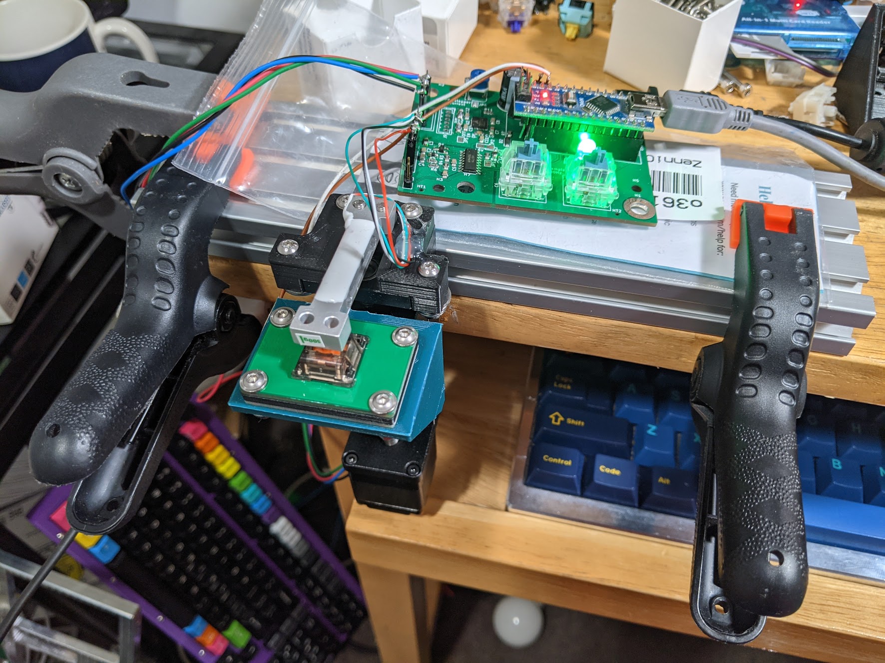
This is an open-source keyboard switch force-curve tester for MX-style switches. Gen 1 is currently operational, and force curves of various switches I've measure are in the Force curve measurements\ directory. Gen 2 has its physical design done, though needs to be built out (I was planning this for a while, but life's gotten in the way); I haven't had a chance to work on it in some time and is unfortunately not a priority for me right now.
This was designed specifically for MX switches to simplify the design and make everything cheaper and more compact, and since most of the switches I am curious about (as well as almost all new switches released today) use the MX form factor. In theory it could be adapted to test say, Alps or other discrete switches (it would need a different plate and switch holder). This is not as versatile as force-curve testers built around a test stand (like the one Haata built) and can't test arbitrary keyboards like that one, but it's much cheaper to build (I spent about $200 building this, and in theory this is buildable for ~$100 if one foregoes the custom PCB and order the parts from China)
This project is licensed under the CERN OHL-S (strongly reciprocal) license for the hardware designs and the software. This is a share-alike license, and if you modify the project files you are required to also open-source your modifications.
The force curve graphs themselves - the .ODS spreadsheets and the .PNG images of the graphs in the Force curve measurements\ folder - are licensed under Creative Commons CC-BY 4.0.
There is also an RGBLED (on board on Gen 1, on the Adafruit RP2040 board on Gen 2) for status indication, and MX switches (2 on Gen 1, 4 on Gen 2) for control.
The CAD was done in Alibre Atom3D. STEP files are provided. All fasteners used on Gen 1 are M3x0.5. Gen 2 uses a mix of M3 and M5 fasteners.
Gen 1 and Gen 2 both have custom PCBs, designed in KiCAD. You will need KiCAD V6 to open the files. In theory, a PCB is not necessary - you can build this on perfboard, as off-the-shelf HX711 modules are available from Sparkfun and elsewhere, and you can steper motor drivers on breadboard-friendly breakout board. However, it makes things a lot neater.
Gen 1's firmware is written in Arduino. Gen 2's firmware still needs to be written (I am still deciding between doing it in C, Rust, CircuitPython, or Arduino).
The HX711 is powered off the microcontroller's 5V supply. The stepper motor is powered off a separate external 12V power supply, though some steppers might work off 5V, and there is a solderable jumper if you want to try powering the stepper off the Arduino's 5V. Having the stepper powered separately is useful though, as I can do dry-run tests on the code with the power supply disconnected (preventing motor movement), and I can also disconnect the power supply if I need to stop the stepper for some reason.
The switch is mounted on a small switchplate. On this one I made it out of FR4 so I could get it made at the PCB fab, but I provided a DXF file if you want it laser-cut. There is a second PCB that connects the switch to a hotswap socket, for measuring the switch's actuation point.
On Gen 1, The firmware initiates a test cycle when you press the left button (light goes from white to green). You can move the switch towards the load cell with the right button before the test cycle. Data is sent via Arduino Serial Monitor - you can then copy/paste the data into a spreadsheet, process the data, and graph it to generate a curve. The switch is moved towards the load cell as long as the force reading is <120gf (this limit is configurable), and automatically reverses when that value is exceeded. When the reversal happens, the LED goes from green to red. The stepper motor drives the stage back to start position, and is yellow when everything is done. At the end of the test cycle, you can press the right button to move the switch away from the load cell.
Hardware
Firmware
Various content (planned)
Possible long-term improvements:
Ruddy, who's affiliated with GeekBoards.ru, independently developed a similar force curve meter and open-sourced his design on Github here. His measurements are here
HaaTa, who founded Input Club, and well known for his force curve measurements. His design is on Github here and described on Deskthority here, and results are on Plotly here
Nebulant and ManOfInterests also possess force curve meters, though I am not aware of any centralized location they publish their measurements. You can find their graphs on their Instagrams, across various Discord servers, Twitter, and on Keebtalk.
Romly built a force curve meter over in Japan. Details here.
Theremingoat has a force curve meter and now has a massive respository.
| Qty | Value | Footprint | References |
|---|---|---|---|
| 4 | D_Zener | Diode_THT:D_DO-41_SOD81_P7.62mm_Horizontal | D1, D3, D4, D5 |
| 4 | SW_Push | Button_Switch_Keyboard:SW_Cherry_MX_1.00u_PCB | SW1, SW2, SW3, SW4 |
| 3 | MountingHole | MountingHole:MountingHole_3.2mm_M3_ISO7380 | H2, H3, H4 |
| 2 | 100uF 35V | Capacitor_THT:CP_Radial_D8.0mm_P3.50mm | C1, C3 |
| 1 | 2A | Capacitor_THT:C_Disc_D10.5mm_W5.0mm_P5.00mm | F1 |
| 1 | Arduino_Nano_v3.x | Module:Arduino_Nano | A2 |
| 1 | Barrel_Jack_MountingPin | Connector_BarrelJack:BarrelJack_Horizontal | J1 |
| 1 | Conn_01x04 | TerminalBlock_Phoenix:TerminalBlock_Phoenix_MKDS-1,5-4_1x04_P5.00mm_Horizontal | J8 |
| 1 | Conn_01x08 | Connector_PinSocket_2.54mm:PinSocket_1x08_P2.54mm_Vertical | J3 |
| 1 | Conn_02x05_Odd_Even | Open-Switch-Tester-parts:2x05-P2.54mm-Shrouded-Keyed-Header | J2 |
| 1 | MountingHole_Pad | MountingHole:MountingHole_3.2mm_M3_ISO7380_Pad | H1 |
| 1 | NeoPixel_THT | LED_THT:LED_D5.0mm-4_RGB | LED1 |
| 1 | StepStickGeneric | StepStick:StepStickGeneric | U2 |
VoronDesign/Voron-Hardware
Cool Hardware designed by the Voron Design group

hoglet67/RGBtoHDMI
Bare-metal Raspberry Pi project that provides pixel-perfect sampling of Retro Computer RGB/YUV video and conversion to HDMI

hackclub/OnBoard
💡 Join 1,000 teenagers and make your first PCB with a $100 grant!

abhishek-kakkar/BeagleLogic
A Software Suite that implements a logic analyzer with the PRU on the BeagleBone / BeagleBone Black.

Chrismettal/flipper-zero-backpacks
Backpack-style addon boards for the Flipper Zero!


CRImier/MyKiCad
My KiCad boards. Can't be bothered uploading individually anymore, so here you go.
It measures 140 × 50 mm and has 2 copper layers, 1.6 mm thick.
22 parts. The full list of its parts is on this page, with links to each part's symbol and footprint where PCBKit's library has them.
From the stack-knight6uy/Open-Switch-Curve-Meter repository on GitHub, at the commit this page was made from: the board is Gen 2 Design/PCB/Main-board-ArduinoNano/Main-board-ArduinoNano.kicad_pcb and its schematic Gen 1 Design/PCB files/FR4 switchplate/plate/plate.kicad_sch. PCBKit opens the board in the browser, with nothing to install.
Its repository states no licence, so its author keeps all rights: ask stack-knight6uy before reusing the design.