2 layers94 × 70 mm

 SRB2149/SR-CRT3
A HDMI-to-GT65 Adapter. Uses a USB Capture Card, Raspberry Pi, Tang Nano 9K and a custom interface PCB to bring your Amstrad GT65 40 years into the future.
SR CRT is an open-source printed circuit board by SRB2149, from the SRB2149/SR-CRT repository on GitHub, published under the MIT licence. It is a 4-layer board of 42.5 × 33.3 mm with 20 parts on 17 nets, routed with 188 tracks and 26 vias.
It is built around the ADUM1200BR and SN65LVDS2DBV. Its parts include 8 capacitors, 4 resistors, 3 ICs and 3 connectors. It belongs with the interfaces and adapters boards of this library.


Live HDMI video on a vintage monochrome CRT, via a Raspberry Pi, an FPGA and a custom interface PCB.
A desktop PC outputs HDMI to a USB capture card on a Raspberry Pi Zero 2 W. The Pi downscales the feed to 296x256, dithers it to 1 bit per pixel using Atkinson dither, and streams it over SPI to an FPGA. The FPGA then drives the Amstrad GT65 CRT monitor at 50 Hz.
PC --HDMI--> Capture Card --USB--> Pi --SPI--> FPGA --LVDS--> Interface PCB --Serial--> CRTThe Pi does the heavy lifting in software (capture, scale, dither). The FPGA does the time-critical CRT signal generation in hardware. SPI between them runs at 50 MHz and carries one 9472-byte framebuffer per CRT frame. The interface PCB acts as a level shifter as well as (depending on the setup) an electrical isolator. In theory the CRT could be directly driven using a level shifter from the FPGA, but you are on your own if you wish to attempt that.
In Windows 11 itself the monitor is set to 640x480 at 60 Hz.
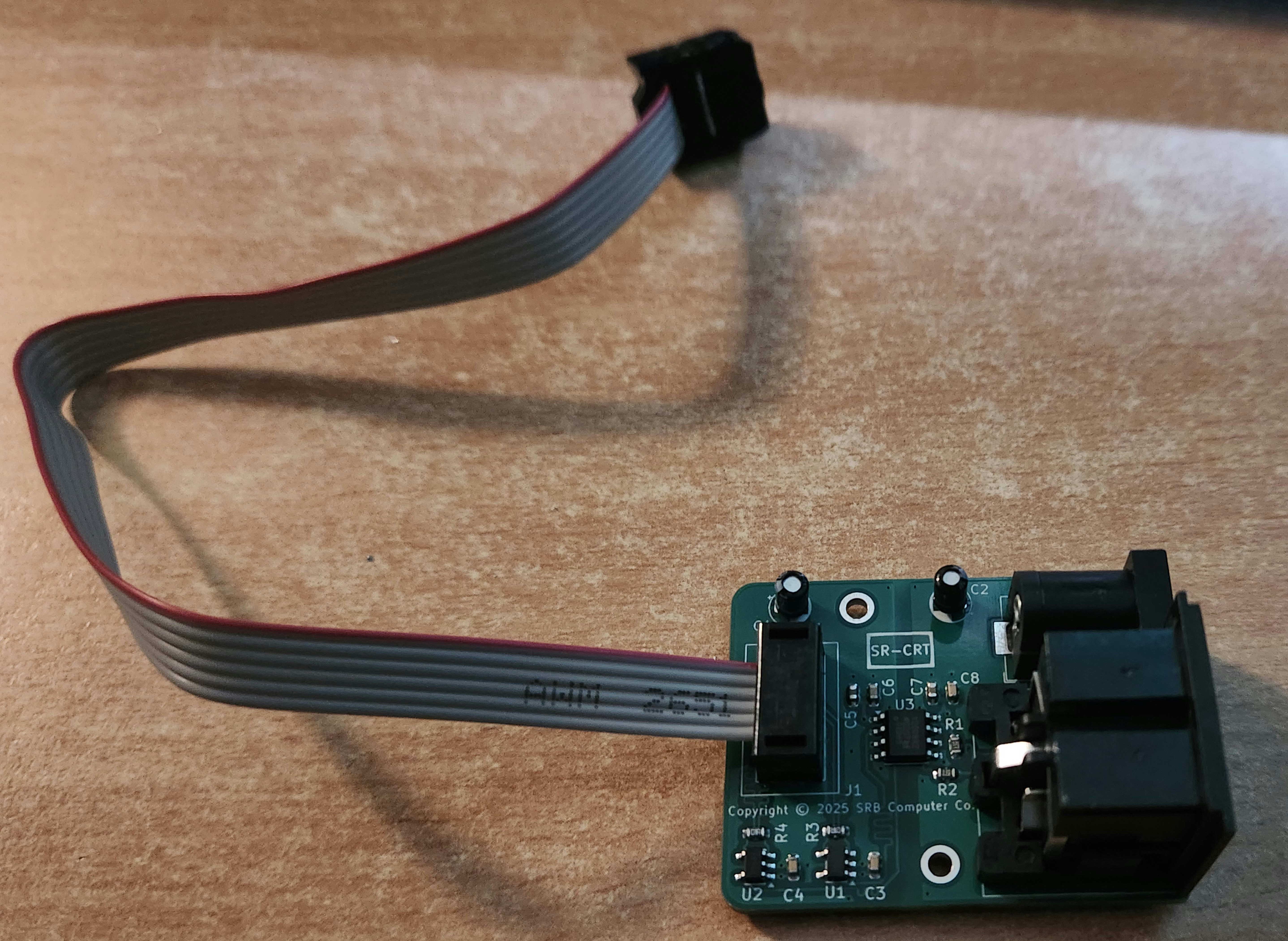
The custom interface PCB once assembled
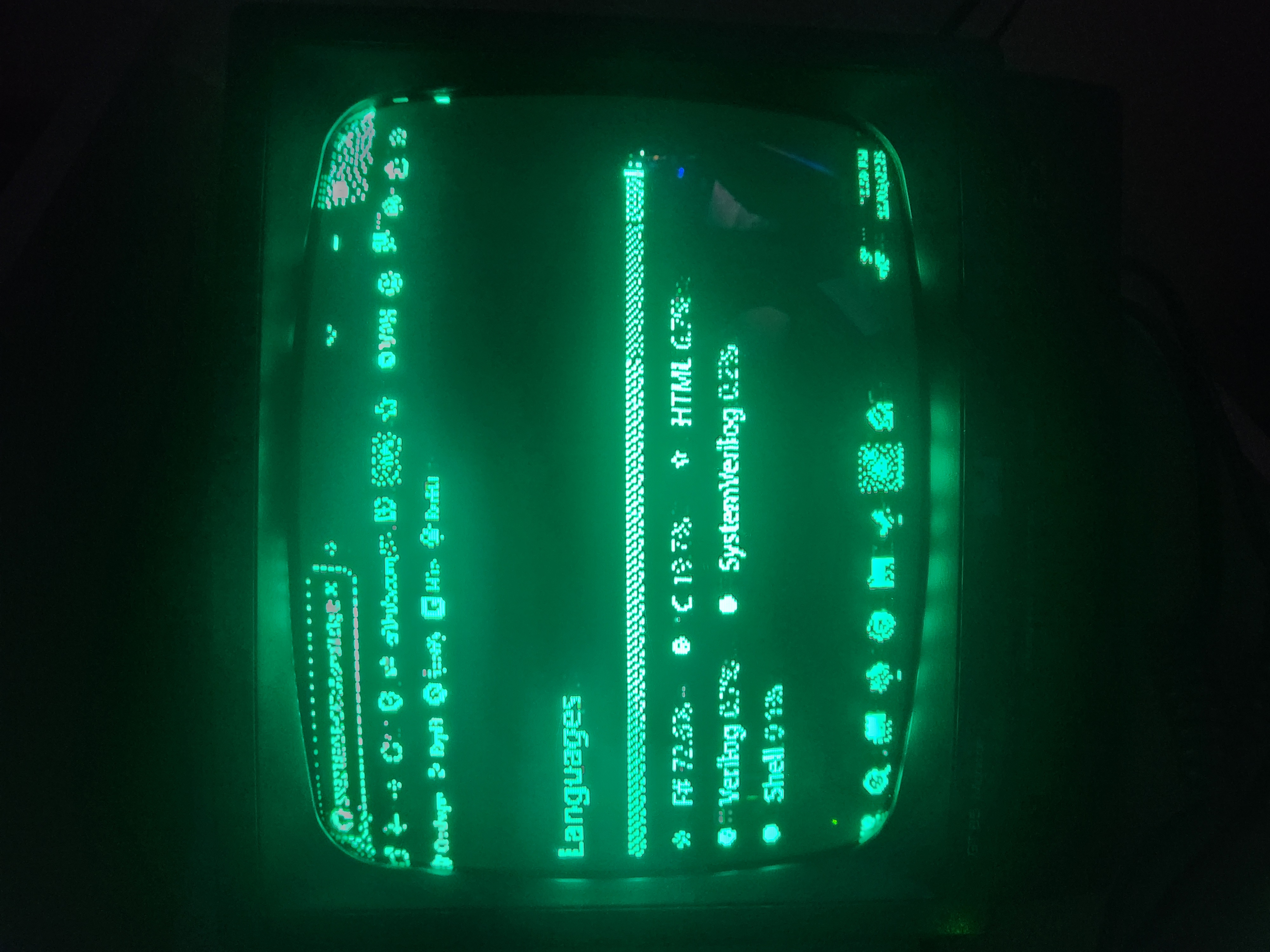
Here is the CRT showing the languages section of this repo!
For the Raspberry Pi side, see INSTALL.txt. The short version:
scp the contents of RPi/ to the Pi./setup_pi.sh and rebootFor the FPGA side, open the project in your toolchain of choice and flash to your board. Pin assignments are in the top-level constraints file. You can flash the SPI_to_CRT.fs binary file directly if you have a GW1NR-LV9C (Tang Nano 9K) FPGA. Otherwise you will need to resynthesise etc.
The Raspberry Pi software was written by Claude (Anthropic) under my supervision. The FPGA work and the rest is mine. For enquiries, contact contact@stanleybooth.uk.
This project is licensed under the MIT License — see LICENSE for details.
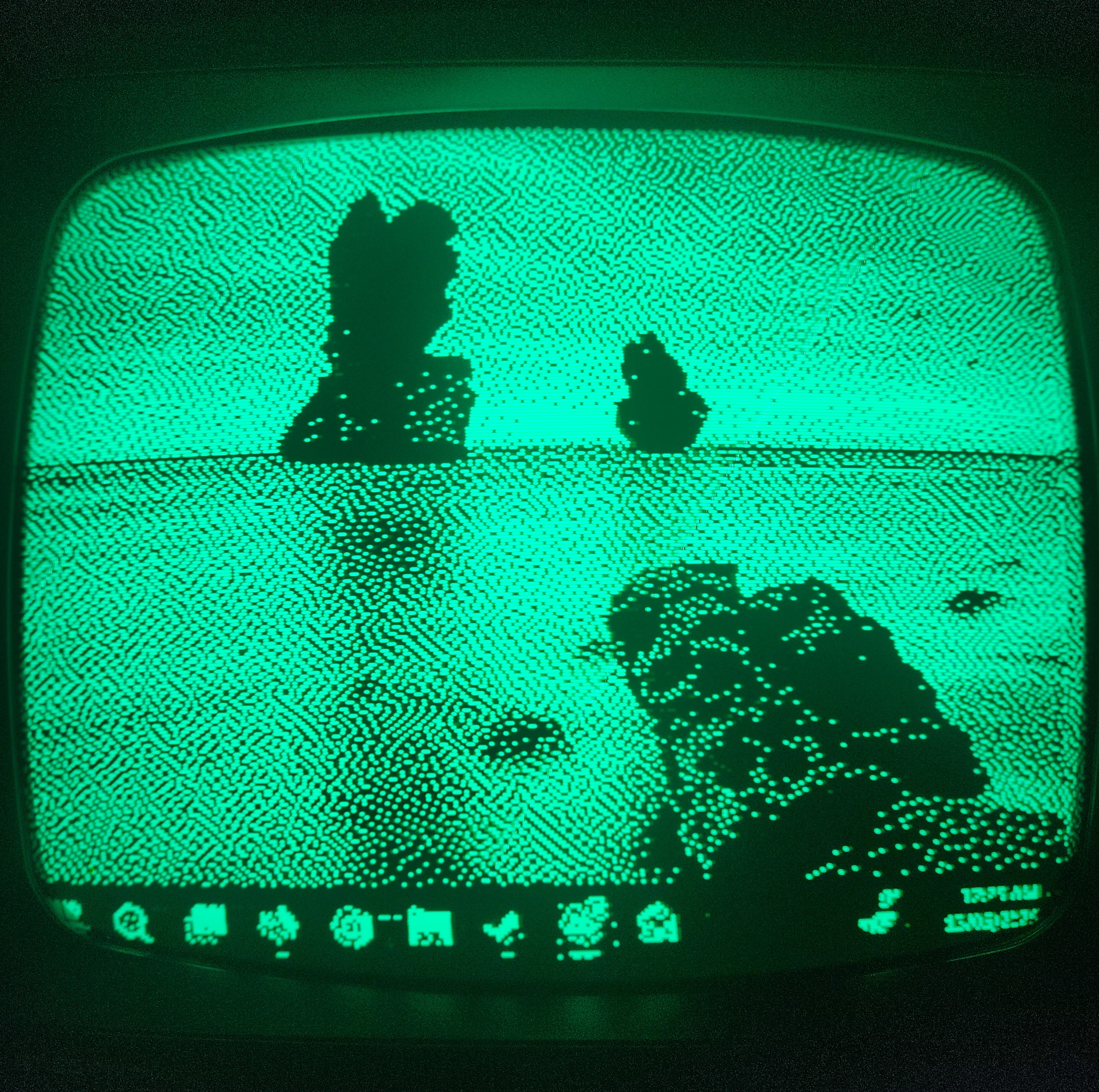
Here are some more photos of the CRT in action. These photos do not capture the real feeling of the CRT particularly well. It looks much better in real life, especially when displaying videos or things that move as the ghosting leaves a very cool effect. The dithering also provides an incredible amount of information given the limited pixels. It really has to be seen in person to truly appreciate.
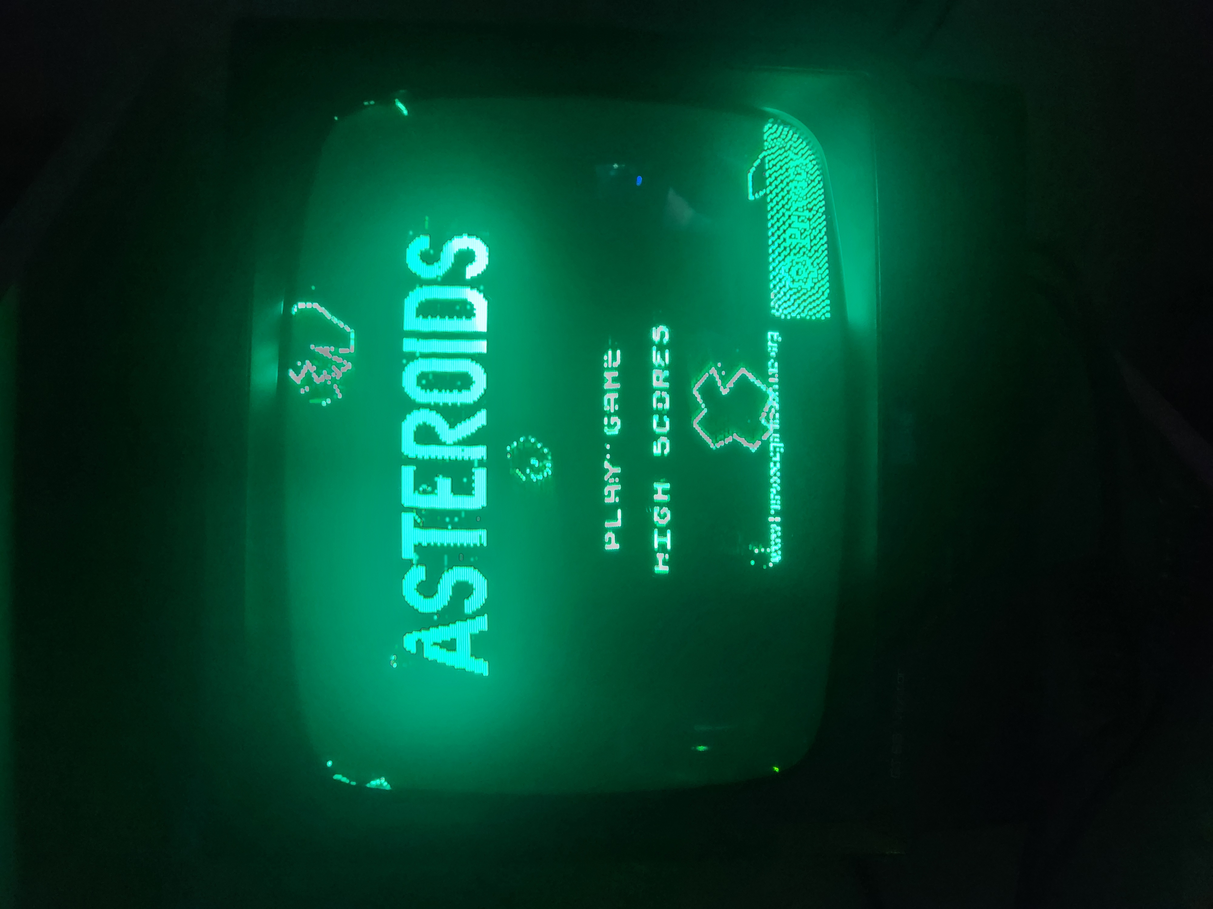 Asteroids online
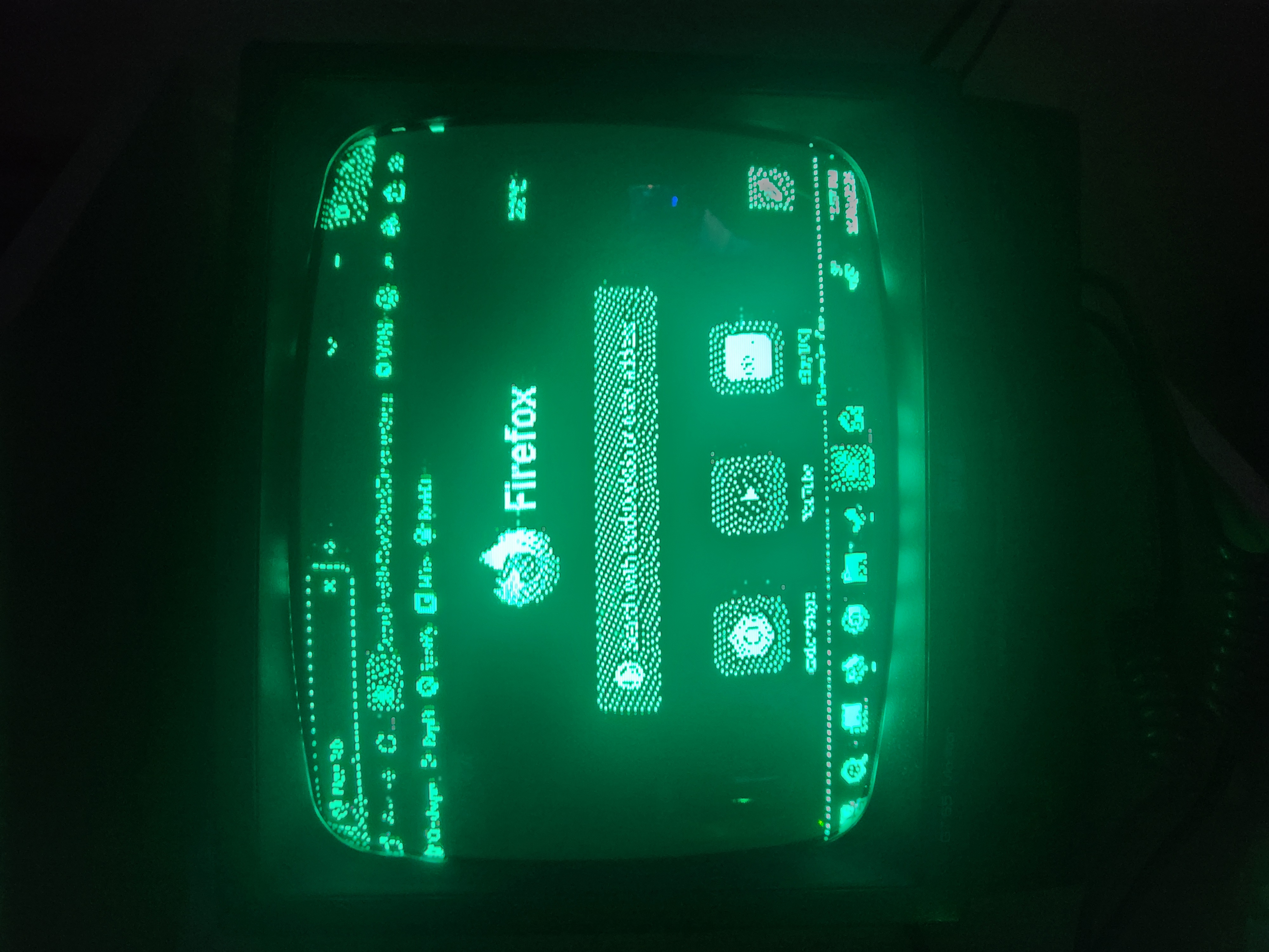 Firefox
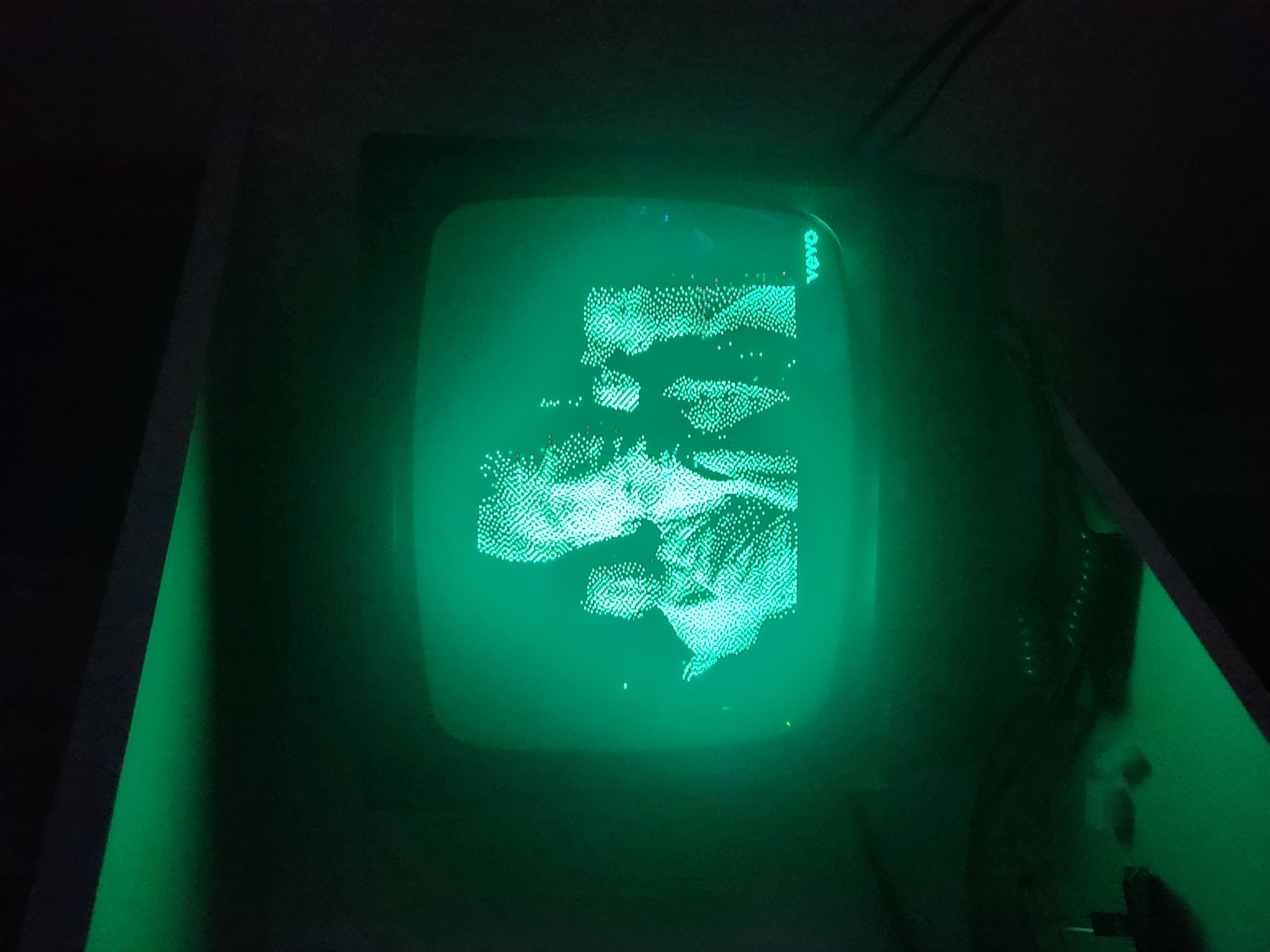 A frame from the song "Hip to Be Square" by Huey Lewis and the News on youtube.
| Qty | Value | Footprint | References |
|---|---|---|---|
| 4 | 100n | Capacitor_SMD:C_0603_1608Metric | C3, C4, C6, C8 |
| 2 | 100 | Resistor_SMD:R_0603_1608Metric | R3, R4 |
| 2 | 10u | Capacitor_THT:CP_Radial_D4.0mm_P2.00mm | C1, C2 |
| 2 | 1u | Capacitor_SMD:C_0603_1608Metric | C5, C7 |
| 2 | 33 | Resistor_SMD:R_0603_1608Metric | R1, R2 |
| 2 | MountingHole | MountingHole:MountingHole_2.2mm_M2_ISO7380_Pad_TopBottom | H1, H2 |
| 2 | SN65LVDS2DBV | Package_TO_SOT_SMD:SOT-23-5 | U1, U2 |
| 1 | ADuM1200BR | Package_SO:SOIC-8_3.9x4.9mm_P1.27mm | U3 |
| 1 | Barrel_Jack_MountingPin | Connector_BarrelJack:BarrelJack_Horizontal | J2 |
| 1 | Conn_02x03_Odd_Even | Connector_IDC:IDC-Header_2x03_P2.54mm_Vertical | J1 |
| 1 | DIN-6 | CustomFootprints:6_PIN_DIN | J3 |
It measures 42.5 × 33.3 mm and has 4 copper layers, 1.6 mm thick.
20 parts, built around the ADUM1200BR and SN65LVDS2DBV. The full list of its parts is on this page, with links to each part's symbol and footprint where PCBKit's library has them.
From the SRB2149/SR-CRT repository on GitHub, at the commit this page was made from: the board is PCB/sr-crt.kicad_pcb and its schematic PCB/sr-crt.kicad_sch. PCBKit opens the board in the browser, with nothing to install.
Its repository publishes it under the MIT licence: you may reuse it on that licence's terms (keep the author's notice, and for a copyleft licence share your changes alike).

macnetic/rp2040-cubesat
A CubeSat Onboard Computer, using the RP2040 microcontroller.

hennichodernich/SFP-Breakout-SE
A breakout board for SFP modules, based on aewallin's work

MarSik/hf-sampling-trx
Portable transceiver based on quadrature sampling detector/exciter

tcfh2003/Virtex-6-ML602-ADCDAC-PCB
PCB for an ADCDAC FPGA Mezannine Card for the ML602 Virtex 6 Evaluation Board


hackclub/OnBoard
💡 Join 1,000 teenagers and make your first PCB with a $100 grant!