
2 layers94 × 90 mm
ButtonLEDsController
spotlesscoder/SmartClockHardware_ControlUnit
This is part of the the hardware specification for my smart clock project.
39 parts
 spotlesscoder/SmartClockHardware_ControlUnit
This is part of the the hardware specification for my smart clock project.
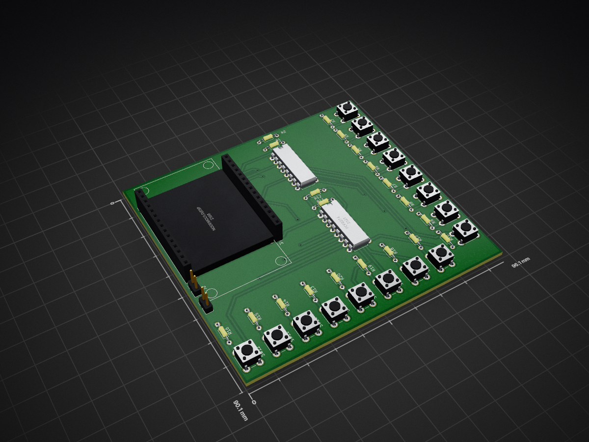
ControlUnitInput is an open-source printed circuit board by spotlesscoder, from the spotlesscoder/SmartClockHardware_ControlUnit repository on GitHub. It is a 2-layer board of 96.1 × 90.1 mm with 43 parts on 59 nets, routed with 242 tracks and 9 vias.
It is built around the PCF8574T. Its parts include 20 resistors, 16 switches, 4 connectors and 3 ICs. It belongs with the ESP8266 boards of this library.
This is part of the the hardware specification for my smart clock project.
The hardware consists of one device for the wake-up light functionality and another for the controls and LCD display.
The control unit with the display again, consists of 3 major parts held in one encasing
1.1) The controller for the input devices: various buttons and a PIR motion sensor. There are many buttons for quite a lot of different features. As the NodeMCU doesn't have enough pins, two PCF8574 IO expander chips are used (yes, I tried the MCP23017 but didn't like the libraries and didn't want to write a new one).
1.2) The Mega2560 devboard with a 2.8" touch display shield on it and the two other parts (1.1 and 1.3) connected via hardware serials.
1.3) The NodeMCU controlling the illuminated button's lights. Two buttons have RGB leds in the which can be controlled separately. The other 9 buttons have single colour LEDs. All of the button's LEDs can be adjusted to different brightness levels, together with the LCD panel's backlight brightness.
| Qty | Value | Footprint | References |
|---|---|---|---|
| 16 | 10k | Resistors_THT:R_Axial_DIN0204_L3.6mm_D1.6mm_P7.62mm_Horizontal | R3, R4, R5, R6, R7, R8, R9, R10, R13, R14, R15, R16, R17, R18, R19, R20 |
| 15 | SW_Push | Buttons_Switches_THT:SW_PUSH_6mm_h8mm | SW1, SW2, SW3, SW4, SW5, SW6, SW7, SW8, SW9, SW10, SW11, SW13, SW14, SW15, SW16 |
| 4 | 4.7k | Resistors_THT:R_Axial_DIN0204_L3.6mm_D1.6mm_P7.62mm_Horizontal | R1, R2, R11, R12 |
| 2 | Pin_Headers:Pin_Header_Straight_1x15_Pitch2.54mm | J3, J4 | |
| 2 | Pin_Headers:Pin_Header_Straight_1x02_Pitch2.54mm | J1, J2 | |
| 1 | Housings_DIP:DIP-16_W7.62mm | U2 | |
| 1 | Buttons_Switches_THT:SW_PUSH_6mm_h8mm | SW12 | |
| 1 | NodeMCU1.0(ESP-12E) | NodeMCU:NodeMCU1.0(12-E) | U1 |
| 1 | PCF8574 | Housings_DIP:DIP-16_W7.62mm | U3 |
It measures 96.1 × 90.1 mm and has 2 copper layers, 1.6 mm thick.
43 parts, built around the PCF8574T. The full list of its parts is on this page, with links to each part's symbol and footprint where PCBKit's library has them.
From the spotlesscoder/SmartClockHardware_ControlUnit repository on GitHub, at the commit this page was made from: the board is ControlUnit/ControlUnitInput/ControlUnitInput.kicad_pcb. PCBKit opens the board in the browser, with nothing to install.
Its repository states no licence, so its author keeps all rights: ask spotlesscoder before reusing the design.
spotlesscoder/SmartClockHardware_ControlUnit
This is part of the the hardware specification for my smart clock project.


NuttyShell/NuttyBadge
NuttyBadge: A NuttyShell crafted multi-tool. Opensourced Hardawre and Software


0Zane/Nomad
One Adventure - One device,Nomad is a custom outdoor mobile device built around the ESP32-S3. It is designed for explorers, researchers, and outdoor enthusiasts who need reliable positioning, long-range communication…