

2 layers309.6 × 95.3 mm
Macrolev
heiso/macrolev
Macrolev is an open source analog keyboard powered by Hall Effect switches
184 parts136
 Spb2005/Thrustmaster-T248-reverse-engineering17
Reverse engineering project of the Thrustmaster T248 steering wheel, with the end goal, of making custom steering wheels for it.
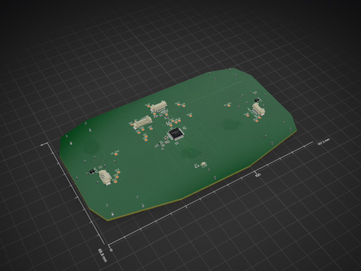
T248 Reverse engeneer is an open-source printed circuit board by Spb2005, from the Spb2005/Thrustmaster-T248-reverse-engineering repository on GitHub, published under the MIT licence. It is a 2-layer board of 147.2 × 86.8 mm with 76 parts on 38 nets, routed with 439 tracks and 67 vias.
It is built around the A1101ELHLT-T. Its parts include 10 resistors, 8 capacitors, 3 ICs and 1 transistor. It belongs with the STM32 boards of this library.



A fully reverse-engineered custom steering wheel running on a stock Thrustmaster T248 wheelbase.
This project documents the analysis of the T248 UART protocol, hardware architecture, and firmware behavior, enabling electronic emulation of the original wheel using an RP2040 microcontroller.
⚠️ This project involves hardware modification. Build and use it at your own risk.
The mechanical base of this wheel is based on the Turn Vantage GTE DIY Sim Racing Wheel from Turn Racing. I modified it to suit my needs.
This project focuses on reverse engineering the Thrustmaster T248 steering wheel in order to enable fully custom-built steering wheels on a stock T248 wheelbase.
The long-term objective is to fully understand the communication protocol, hardware architecture, and firmware structure well enough to electronically emulate the original wheel.
All detailed technical documentation (protocol captures, PCB reverse engineering, firmware analysis, oscilloscope measurements, etc.) has been moved to the Wiki to keep this README clean and focused.
👉 Full Technical Documentation (Wiki)
The emulator is implemented using:
Other 3.3V microcontrollers may be used, but voltage compatibility must be strictly verified. And additional code changes might be necessary.
Development was carried out incrementally through multiple V1.x versions (documented in the Wiki: 4. Wheel Emulator ).
The first stable and practically usable version is V2.0
This version is considered the first fully working implementation suitable for real-world use.
DEBUG flag to disable serial debugging outputCode:
👉 T248_Emulator_V2.0.ino
Schematic:

Notes:
Example cable colors (may vary):
⚠️ Wire colors may differ between units.
The safest method is verifying each wire against the steering wheel PCB test pads:
More information:
👉 Hardware Analysis (Wiki)
⚠️ IMPORTANT WARNING
⚠️Never connect the Pico to USB while it is electrically connected to the wheelbase.
The VSYS voltage can exceed 3.3V and permanently damage the wheelbase electronics.
⚠️ This project involves hardware modification.
You are responsible for any damage to your equipment.
Before the full emulator was completed, a USB-only custom steering wheel implementation was developed.
Characteristics:
This version does not communicate with the T248 wheelbase and requires a separate USB connection to the PC.
The following areas still require further investigation:
.tmf file?The objective of this project is to:
This concept is similar to what Taras demonstrated on his blog, where he used Arduino code to emulate older Thrustmaster models (T150, TMX, T300, etc.).
All detailed research material is available in the Wiki:
| Qty | Value | Footprint | References |
|---|---|---|---|
| 24 | TestPoint | TestPoint:TestPoint_Pad_D1.5mm | TP1, TP2, TP3, TP10, TP11, TP12, TP13, TP14, TP15, TP16, TP17, TP18, TP19, TP20, TP21, TP22 +8 |
| 17 | SW_Push | Button_Switch_SMD:Rubberdome PCB Steering Wheel | BTN_3, BTN_4, BTN_5, BTN_6, BTN_7, BTN_8, BTN_9, BTN_10, BTN_11, BTN_12, BTN_13, BTN_18_DISPLAY1, BTN_19_MODE1, DPAD_DOWN1, DPAD_LEFT1, DPAD_RIGHT1 +1 |
| 6 | C | Capacitor_SMD:C_0402_1005Metric_Pad0.74x0.62mm_HandSolder | C1, C2, C3, C4, C6, C10 |
| 4 | TestPoint | TestPoint:TestPoint_Keystone_5015_Micro-Minature | J_DEBUG_1, J_DEBUG_5, J_DEBUG_6, J_DEBUG_10 |
| 3 | TestPoint | TestPoint:TestPoint_Pad_1.0x1.0mm | J_DEBUG_2, J_DEBUG_3, J_DEBUG_9 |
| 2 | 100 | Resistor_SMD:R_0603_1608Metric_Pad0.98x0.95mm_HandSolder | R7, R12 |
| 2 | 10k | Resistor_SMD:R_0402_1005Metric_Pad0.72x0.64mm_HandSolder | R1, R2 |
| 2 | 27.5 | Resistor_SMD:R_0402_1005Metric_Pad0.72x0.64mm_HandSolder | R5, R14 |
| 2 | A1101ELHL | Package_TO_SOT_SMD:SOT-23W | U2_L1, U3_R1 |
| 2 | C | Capacitor_SMD:C_0603_1608Metric_Pad1.08x0.95mm_HandSolder | C5, C8 |
| 2 | Conn_01x04 | Connector_Molex:Molex_PicoBlade_53261-0471_1x04-1MP_P1.25mm_Horizontal | J_20-21_BTN1, J_22-23_BTN1 |
| 1 | 0 | Resistor_SMD:R_0603_1608Metric_Pad0.98x0.95mm_HandSolder | R4 |
| 1 | 0.5 | Resistor_SMD:R_0402_1005Metric_Pad0.72x0.64mm_HandSolder | FB1 |
| 1 | 33 | Resistor_SMD:R_0402_1005Metric_Pad0.72x0.64mm_HandSolder | R3 |
| 1 | 4.7 k | Resistor_SMD:R_0402_1005Metric_Pad0.72x0.64mm_HandSolder | R13 |
| 1 | 4.7k | Resistor_SMD:R_0402_1005Metric_Pad0.72x0.64mm_HandSolder | R11 |
| 1 | Conn_01x05 | Connector_Molex:Molex_PicoBlade_53261-0571_1x05-1MP_P1.25mm_Horizontal | J_LCD1 |
| 1 | Conn_01x06 | Connector_Molex:Molex_PicoBlade_53398-0671_1x06-1MP_P1.25mm_Vertical | J_WHEEL1 |
| 1 | LED | LED_SMD:LED_0805_2012Metric_Pad1.15x1.40mm_HandSolder | L_S1 |
| 1 | Q_NMOS_DGS | Package_SON:0806 mosfet | Q1 |
| 1 | STM32G030K6Tx | Package_QFP:LQFP-32_7x7mm_P0.8mm | U2 |
It measures 147.2 × 86.8 mm and has 2 copper layers, 1.6 mm thick.
76 parts, built around the A1101ELHLT-T. The full list of its parts is on this page, with links to each part's symbol and footprint where PCBKit's library has them.
From the Spb2005/Thrustmaster-T248-reverse-engineering repository on GitHub, at the commit this page was made from: the board is PCB_Schematic_Files/T248_Reverse_engeneer/T248 Reverse engeneer.kicad_pcb and its schematic PCB_Schematic_Files/T248_Reverse_engeneer/T248 Reverse engeneer.kicad_sch. PCBKit opens the board in the browser, with nothing to install.
Its repository publishes it under the MIT licence: you may reuse it on that licence's terms (keep the author's notice, and for a copyleft licence share your changes alike).
heiso/macrolev
Macrolev is an open source analog keyboard powered by Hall Effect switches


ashton6student/ece445
Note: each subfolder has its own README.md file that forms the ECE 445 notebook, in addition to this top-level file.


joeycastillo/The-Open-Book
For details on how to build, test and use Open Book, I've made documentation available here.

hoglet67/RGBtoHDMI
Bare-metal Raspberry Pi project that provides pixel-perfect sampling of Retro Computer RGB/YUV video and conversion to HDMI

jpconstantineau/ErgoTravel
A Portable Ergonomic Split Keyboard inspired from the ErgoDox, Let's Split and Minidox