2 layers40 × 20 mm
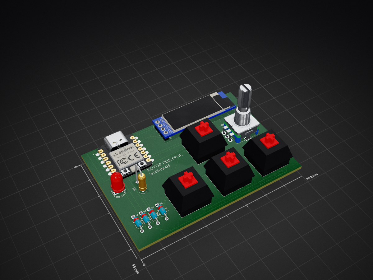
 spacedivee/Satellite-Rotor-Control-1
Grouping of all the files needed to make the controller.
Satellite Rotor Control- is an open-source printed circuit board by spacedivee, from the spacedivee/Satellite-Rotor-Control- repository on GitHub. It is a 2-layer board of 79.5 × 55 mm with 13 parts on 19 nets, routed with 103 tracks and 0 vias.
Its parts include 5 diodes, 2 ICs, 1 resistor and 1 switch.
A custom PCB-based controller designed as a physical interface for controlling software on a computer. It can be used as a general-purpose control pad, with a focus on eventually controlling a satellite antenna rotator (which is another project I am building).
The XIAO RP2040 reads the buttons and rotary encoder and sends their inputs to software running on a computer. The OLED provides feedback to the user. In my case, the OLED will display Azimuth and Elevation as they are being changed so the antenna adjustmenet can be simplified. The Encoder will be used to manually adjust the increment of the motors, such that each press will be greater or smaller, depending on the input. All of the information will then be sent to the XIAO, which will then sent it to my computer as keystroke data (my current method), which my antenna rotator software will then acknowledge.
For the record, this is the only aspect of my project that was completely made by AI. The current firmware is a placeholder and I plan on writing it myself once I have built the board. I believe this is a better way of doing things since I get to actively troubleshoot issues. I hope yall feel the same way about this ❤️.
| Item | Component Name | Qty | Price (USD) | Notes |
|---|---|---|---|---|
| 1 | Seeed XIAO RP2040 | 1 | $19.32 | Main microcontroller |
| 2 | 1N4148 through-hole diodes | 4 | $1.50 | Button/switch matrix |
| 3 | MX-style switches | 4 | $5.99 | Main input buttons |
| 4 | EC11E rotary encoder with switch | 1 | $8.79 | - |
| 5 | 0.91 inch OLED display | 1 | $6.67 | GND-VCC-SCL-SDA pin order |
| 6 | White blank DSA keycaps | 4 | $12.50 | Keycaps for MX switches |
| 7 | M3x16mm screws | 4 | $8.59 | Case assembly |
| 8 | M3x5mmx4mm heat-set inserts | 4 | $8.49 | Case assembly |
| 9 | $10 JLCPCB credit | 1 | $10.00 | PCB manufacturing |
| 10 | LED | 1 | $0.00 | - supplied by me |
| 11 | Resistor | 1 | $0.00 | - supplied by me |
| 12 | Shipping | 1 | $4.20 | |
| Total Estimated Cost: | $86.05 |
Note: If you have an existing hackpad kit available, I would happily accept that as an alternative. It may be more cost-effective and prevents acquiring unnecessary duplicate components.
| Qty | Value | Footprint | References |
|---|---|---|---|
| 4 | 1N4148 | Diode_THT:D_DO-35_SOD27_P7.62mm_Horizontal | D1, D2, D3, D4 |
| 4 | SW_Push | Button_Switch_Keyboard:SW_Cherry_MX_1.00u_PCB | Azimuth-1, Azimuth+1, Elevation-1, Elevation+1 |
| 1 | ER_OLEDM0.91_1x-I2C | OLED091:SSD1306-0.91-OLED-4pin-128x32 | U2 |
| 1 | LED | LED_THT:LED_D5.0mm | D5 |
| 1 | MOUDLE-SEEEDUINO-XIAO | footprints:XIAO-Generic-Hybrid-14P-2.54-21X17.8MM | U1 |
| 1 | R | Resistor_THT:R_Axial_DIN0309_L9.0mm_D3.2mm_P5.08mm_Vertical | R1 |
| 1 | RotaryEncoder_Switch | Rotary_Encoder:RotaryEncoder_Alps_EC11E-Switch_Vertical_H20mm | SW1 |


samyk/magspoof
A portable device that can spoof/emulate any magnetic stripe, credit card or hotel card "wirelessly", even on standard magstripe (non-NFC/RFID) readers.

fossasia/pslab-scripts
Pocket Science Lab - Scripts for Sensor Experiments


willem-pennings/balancing-cube
A cube that balances itself in a corner or edge using reaction wheels

VoronDesign/Voron-Hardware
Cool Hardware designed by the Voron Design group

hoglet67/RGBtoHDMI
Bare-metal Raspberry Pi project that provides pixel-perfect sampling of Retro Computer RGB/YUV video and conversion to HDMI
It measures 79.5 × 55 mm and has 2 copper layers, 1.6 mm thick.
13 parts. The full list of its parts is on this page, with links to each part's symbol and footprint where PCBKit's library has them.
From the spacedivee/Satellite-Rotor-Control- repository on GitHub, at the commit this page was made from: the board is PCB/KiCad Files/yo/yo.kicad_pcb and its schematic PCB/KiCad Files/yo/yo.kicad_sch. PCBKit opens the board in the browser, with nothing to install.
Its repository states no licence, so its author keeps all rights: ask spacedivee before reusing the design.