2 layers
Nrf bga
github-linguist/linguist
Language Savant. If your repository's language is being reported incorrectly, send us a pull request!
12 parts14kMIT

 sp9mrn/DDX
The 'Direct Digital Transceiver' (DDX) project. Some folks call it 'Dhiru's Digital Transceiver' :D
Band MODULE V1 00 is an open-source printed circuit board by sp9mrn, from the sp9mrn/DDX repository on GitHub. It is a 2-layer board of 22.5 × 10 mm with 12 parts on 6 nets, routed with 32 tracks and 47 vias.
Its parts include 7 capacitors, 3 inductors and 2 connectors. It belongs with the radio and wireless boards of this library.
The 'Direct Digital Transceiver' (DDX) project. DDX is a radio transceiver (rig) which is rugged, simple and reliable.
Complete BOM (everything) estimate: 20 to 30 USD (depending on configuration).
For a truly portable backpack setup you can combine DDX-1 with the FT8 Radio Android app.
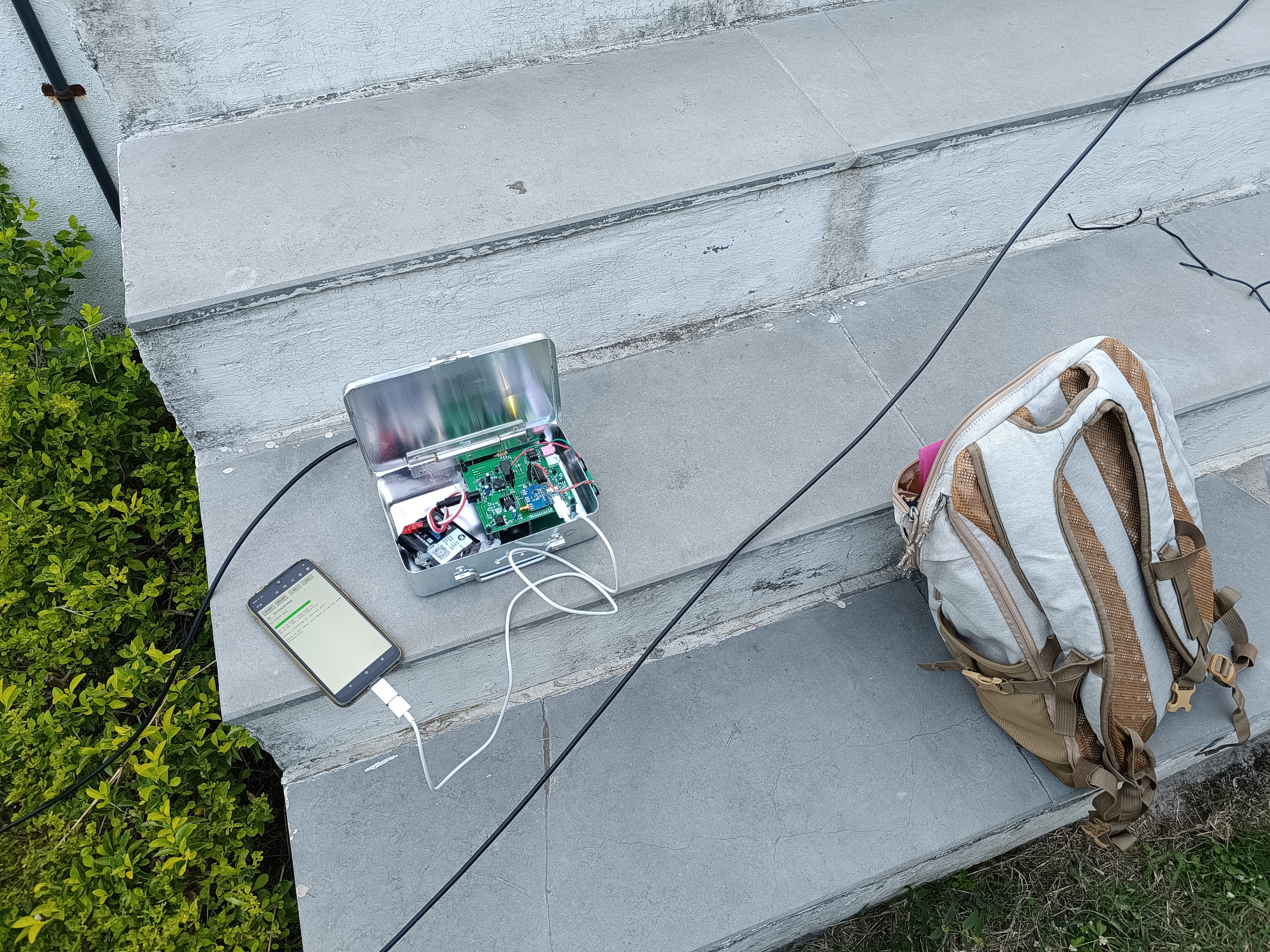
Sample QSO (from Pune to Medellin on 10m, 15691km) on DDX-1:
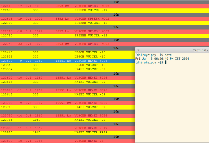
Who doesn't want a QSO from Medellin after binge-watching Narcos? ;)
Single USB-C cable for handling both Audio + CAT control
True 5W output on all HF bands. It even outputs ~1-2 W @ 50 MHz! (We now just need a 6m capable receiver section to build a 6m digital transceiver).
Rock-solid PA which handles open, short, and bad SWR conditions. We knowingly stress-test it with untuned antennas and still manage DX (not a recommended practice for sure though).
Rock-steady VFO which does NOT drift even under exposed conditions. Yes - it receives WSPR at 28 MHz just fine.
Reliable T/R switching based on a DPDT relay
Switchable BPF support to get rid of BCI and other interferences (tested against OTH radar + 100 kW AM station in close visual proximity)
No toroids to wind (assuming an external LPF bank is in use) ;-)
The IRF510 final remains as cool as a cucumber (Class-D operation) - a small heat sink is more than enough.
Avoids problems associated with the 'audio frequency counting' approach used by earlier designs.
It works beautifully with the 'FT8 Radio' app (https://github.com/kholia/DigitalRadioReceiverSupport/). The 'FT8 Radio' app handles FT8 decoding well in real time (Native MCU decoders offer significantly reduced performance at the moment). The app can decode 35++ stations at a time, and even large screens can fill up very rapidly - such is the receiver's performance (with a BPF)!
Supports largely automated assembly from JLCPCB (all the required files are in the same GitHub repository)
DDX-1 comes with a free, open-source AGPLv3 licensed firmware.
No calibration is (ever) required. Just pick up DDX-1 and it is ready to go on air.
Low cost (20 to 30 USD is our BOM estimate)
Stress tested by WSJT-Z for multiple days
DDX-1 routinely receives FT8 traffic from 80 to 100+ countries using a simple 5m long EFHW antenna.
COMMERCIAL USAGE IS FORBIDDEN (aka NOT ALLOWED).
NO SUPPORT and NO GUARANTEE is provided to individuals! This is because we are
a small team, and we want to make progress with maximum velocity to bring you
more goodies. This said, we are willing to help out with the group builds or
club builds of DDX-1 to maximize our dV / dT.
ATTENTION: Using a Si5351 module without a TCXO is a recipe for troubles. You have been warned ("educated").
Note: The firmware is now under AGPLv3 license.
Note 2: Some folders in this repository are encrypted as they are NOT ready for public consumption yet. With time and more testing, more stuff will be released.
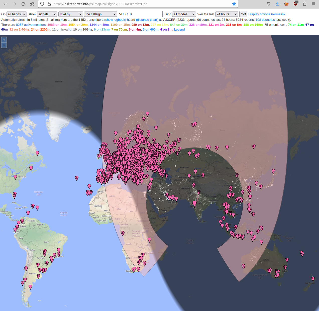
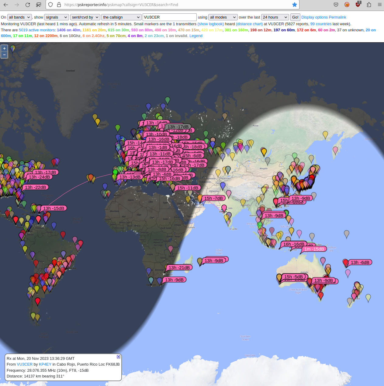
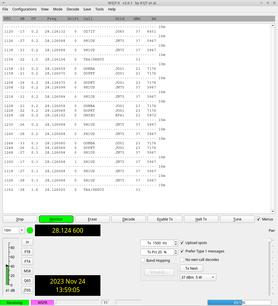
It receives WSPR @ 28 MHz ;)
This is from a HF-PA-v10 board (@ 2W output setting) driving another HF-PA-v10 board with IRF530 installed on it.
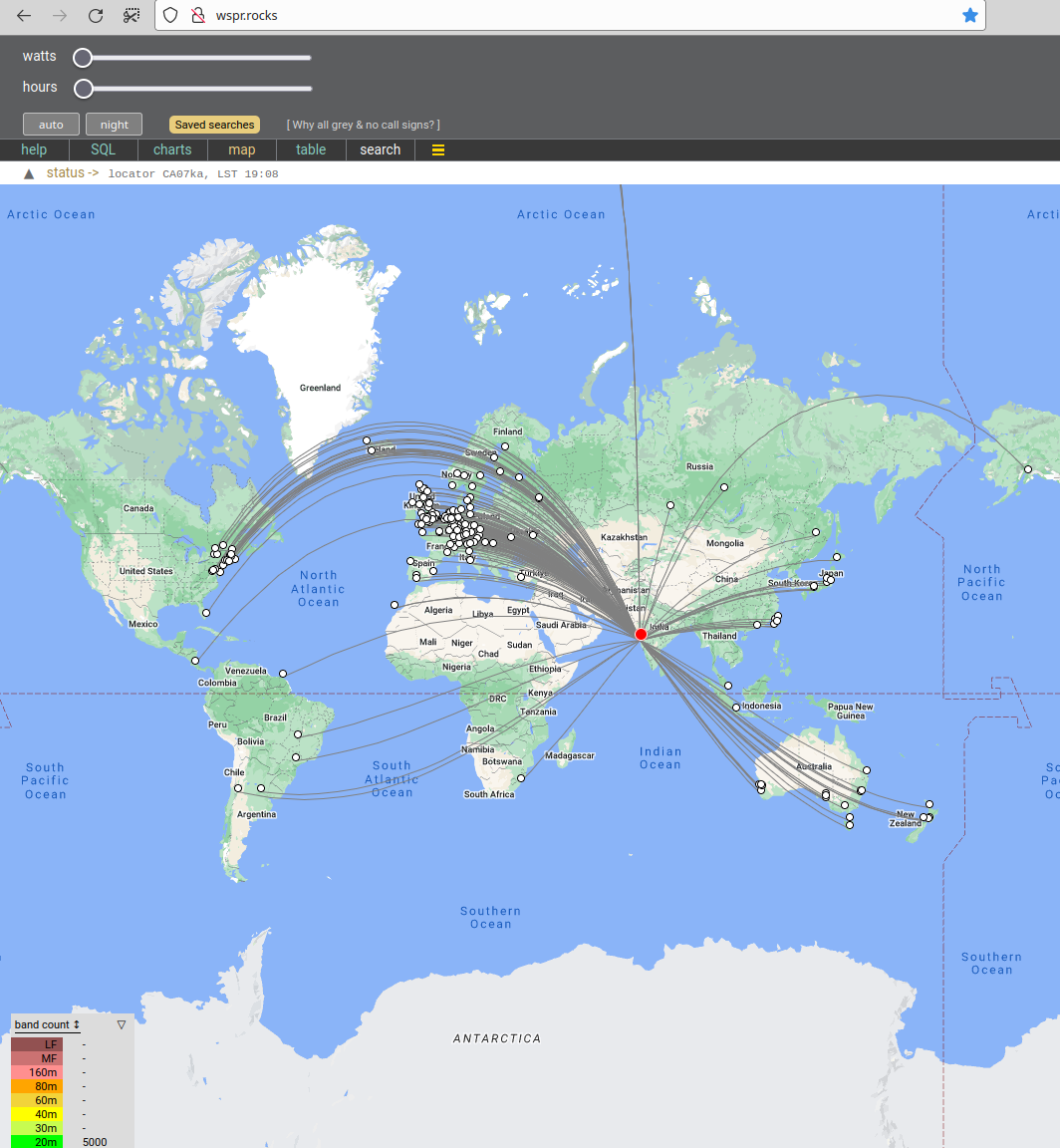
DDX-1 has already made hundreds of QSOs on air.
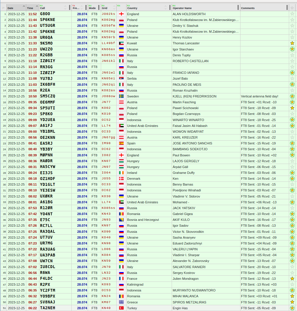
DDX-1-R1.10:
The Pluggable-RX-BPF design did NOT pan out (yet)!
Note: The BPF can be bypassed (by a regular jumper cap) for many use cases. Or a QRP Labs' BPF can be used along with some twisted jumper wires.
We believe in documenting the various failure modes so that we all can learn from them, and produce more rugged designs with time and experience.
After making a few hundred QSOs at home and in local parks, the transmit functionality on DDX-1 became wonky. TX would NOT fire at all, or will fire for only a few seconds.
A quick debugging session indicated that the input power switch (P-Channel AOD407 MOSFET) had failed (gate was shorted with source) with no external visible signs.
This is probably because we skipped installed the D4 diode (5.1v gate
clamping zener diode) in our quick build of the DDX-1 radio.
Solution: We replaced the AOD407 MOSFET and also installed the D4 gate
clamp diode this time ;)
Turn on the main power to the PCB.
Now connect the USB-C cable between DDX and the PC.
See wsjtx_helper/README.md for further steps.
Connect the USB-C cable between DDX and the Android phone.
Turn on the main DC power to the radio.
You may have to explicitly enable the File Transfer mode in USB settings on
your Android device.
With these files, you can get around 80% pre-assembled boards (with the SMD components soldered) from JLCPCB at a minimal cost.
Note: The Si5351+TCXO boards can be ordered in fully assembled form from
JLCPCB. https://github.com/kholia/Si5351-Module-Clone-TCXO/ has the required
files (use the -v3 folder).
JLCPCB link: https://jlcpcb.com/
JLCPCB ordering guide: https://github.com/WB2CBA/ADX-UnO-V1.3/ has the JLCPCB ordering guide in it.
In case of any doubts / confusion, refer to the latest version of the
HF-PA-v10.pdf document. Note: Not everything needs to be populated on the PCB.
Shortcut: Upload the pre-built .uf2 file to the RP2040 Board and skip
to the next section.
Install dependencies:
sudo apt install cmake gcc-arm-none-eabi libnewlib-arm-none-eabi \
  libstdc++-arm-none-eabi-newlib git libusb-1.0-0-dev build-essential \
make g++ gccmkdir ~/repos
cd ~/reposgit clone --recursive https://github.com/kholia/tinyusb.git # use this in pico-sdk
git clone --recursive https://github.com/raspberrypi/pico-sdk.git
git clone --recursive https://github.com/kholia/DDX.gitNow build the firmware using instructions in the firmware_open folder.
Load the built .uf2 file into the MCU board. Process: Hold the BOOT button on
RP2040-Zero, and then connect it to a computer. Release the BOOT button. A new
drive will open on the computer. Just drag the .uf2 firmware file (included in
the repository) to this new drive. Done!
DDX-1 was tested with the following power sources.
RUIDENG DPS5020 power supply module (@13v) powered by MEAN WELL / Mornsun SMPS
3S "12V" Li-ion 18650 battery pack (RECOMMENDED!)
Test DDX-1 end-to-end on Windows (10) and macOS Sonoma.
Upstream major portions of the firmware to the TinyUSB or other projects.
Add code for external tuner control. Use 2mA setting on Si5351 TX during tuning.
Use a Common-Mode-Choke (attached between the rig, and the antenna) for
safety against return/back RF.
[To be confirmed] Wrap a flexible USB-C cable around FT140-43 toroid to create a Common-Mode-Choke (CMC).
https://github.com/WB2CBA/ADX (the design that started it all)
http://www.learningaboutelectronics.com/Articles/Low-pass-filter-calculator.php
https://github.com/kholia/ConsensusBasedTimeSync (receiver comes from here)
https://github.com/kholia/Si5351-Module-Clone-TCXO/ (VFO comes from here)
https://github.com/kholia/HF-PA-v10 (PA comes from here)
Ruggedness philosophy: https://www.youtube.com/watch?v=4r7wHMg5Yjg
https://www.kk5jy.net/three-wire-gp/ (recommended antenna - superb for DX)
https://github.com/kholia/HF-Balcony-Antenna-System (another portable antenna setup)
Are you interested in such projects, and spam-free technical discussions?
If yes, you might be interested in joining the 'HAMBREWERS' Telegram group.
| Qty | Value | Footprint | References |
|---|---|---|---|
| 3 | 100n | Inductor_SMD:L_1210_3225Metric_Pad1.42x2.65mm_HandSolder | L1, L2, L3 |
| 2 | 16p | Capacitor_SMD:C_0805_2012Metric_Pad1.18x1.45mm_HandSolder | C3, C5 |
| 2 | 240p | Capacitor_SMD:C_0805_2012Metric_Pad1.18x1.45mm_HandSolder | C2, C6 |
| 2 | 47p | Capacitor_SMD:C_0805_2012Metric_Pad1.18x1.45mm_HandSolder | C1, C7 |
| 1 | 270p | Capacitor_SMD:C_0805_2012Metric_Pad1.18x1.45mm_HandSolder | C4 |
| 1 | Antenna | footprints:PinHeader_1x3_P2.54mm_Drill1.02mm_Modded_2 | J1 |
| 1 | Input | footprints:PinHeader_1x3_P2.54mm_Drill1.02mm_Modded_2 | J2 |
It measures 22.5 × 10 mm and has 2 copper layers, 1.6 mm thick.
12 parts. The full list of its parts is on this page, with links to each part's symbol and footprint where PCBKit's library has them.
From the sp9mrn/DDX repository on GitHub, at the commit this page was made from: the board is Pluggable-BPF-Design/Band_MODULE_V1_00.kicad_pcb and its schematic BPF-Compat/Band_MODULE_V1_00.kicad_sch. PCBKit opens the board in the browser, with nothing to install.
Its repository states no licence, so its author keeps all rights: ask sp9mrn before reusing the design.
github-linguist/linguist
Language Savant. If your repository's language is being reported incorrectly, send us a pull request!


google/mozc-devices
Circuit diagrams and firmware source code for Gboard DIY keyboards


hackclub/OnBoard
💡 Join 1,000 teenagers and make your first PCB with a $100 grant!

VoronDesign/Voron-Tap
Tap is a nozzle-based z-probe for the V2 and Trident printer designs. The entire toolhead moves to trigger an optical switch. Tap offers many advantages:

stacksmashing/pico-tpmsniffer
A simple, very experimental TPM sniffer for LPC bus