2 layers60 × 30 mm
Controller
google/mozc-devices
Circuit diagrams and firmware source code for Gboard DIY keyboards
11 parts3kApache-2.0

 SP5TLS/rp-keyer1
RP2040 / RP2350 firmware that turns a Raspberry Pi Pico (or Pico 2) into a self-contained CW (Morse) keyer with:
Rp keyer1 is an open-source printed circuit board by SP5TLS, from the SP5TLS/rp-keyer repository on GitHub, published under the Apache-2.0 licence. It is a 2-layer board of 61 × 67 mm with 11 parts on 61 nets, routed with 45 tracks and 0 vias.
Its parts include 4 switches, 3 connectors, 1 resistor and 1 transistor. It belongs with the RP2040 boards of this library.
RP2040 / RP2350 firmware that turns a Raspberry Pi Pico (or Pico 2) into a self-contained CW (Morse) keyer with:
radio-utils-keyer,radio-utils-cw-decoder
feeding the OLED decoded-text row,Pins are grouped into two physical clusters on the Pico header so wiring stays tidy whether you fly leads or build a PCB.
Left edge — keyer hardware:
| Function | Pin | GPIO | Notes |
|---|---|---|---|
| Buzzer / GND | 13 | GND | Shared with radio-key return |
| Buzzer | 14 | GP10 | PWM5A, drives passive piezo |
| Radio key out | 15 | GP11 | Drives 2N2222 base via 1 kΩ resistor |
| Paddle GND | 18 | GND | TRS sleeve |
| Dit paddle | 19 | GP14 | TRS tip, active-low, internal pull-up |
| Dah paddle | 20 | GP15 | TRS ring, active-low, internal pull-up |
Right edge — OLED + 4-button combo module (single 8-wire connector):
| Module pin | Pico pin | GPIO | Function |
|---|---|---|---|
| K1 | 21 | GP16 | Button UP (top of stack) |
| K2 | 22 | GP17 | Button DOWN |
| GND | 23 | GND | Module ground |
| K3 | 24 | GP18 | Button OK |
| K4 | 25 | GP19 | Button BACK (bottom of stack) |
| SDA | 26 | GP20 | I2C0 SDA |
| SCL | 27 | GP21 | I2C0 SCL |
| VCC | 36 | 3V3 | Single jumper to 3V3 OUT |
All eight module wires land on the same edge of the Pico — seven on the contiguous right-side strip (pins 21–27) plus one jumper to 3V3.
   GP11 ─── 1 kΩ ──── Base
                       │
                    2N2222 NPN
                       │
                    ┌──┴──┐
                    │     │
               Collector  Emitter
                    │     │
   radio key tip ───┘     └─── GND ─── radio key sleeve
   (or PTT)
Connections:
Drop a flyback diode across the collector–emitter (cathode to collector) if your radio's key line is inductive.
The schematic uses a 2N3904 in this position; a 2N2222 is a drop-in substitute — both are general-purpose NPN signal transistors with more than enough current capacity for keying a typical radio.
A KiCad 8 project for the reference carrier board lives under
schematics/rp-keyer/. It contains:
rp-keyer1.kicad_pro — project file (open this in KiCad)rp-keyer1.kicad_sch — schematicrp-keyer1.kicad_pcb — PCB layout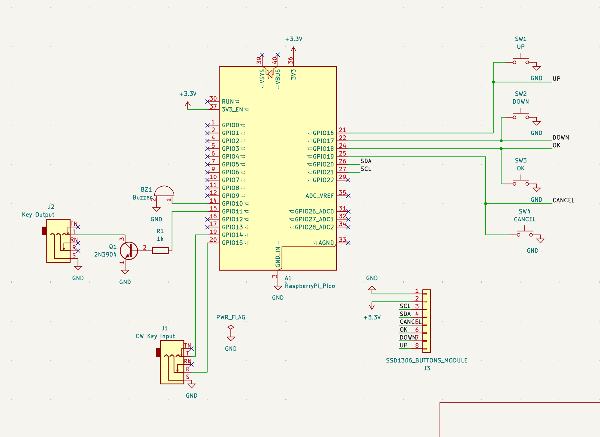
The schematic captures the pinout above 1:1: paddle TRS jack J1 on
GP14/GP15, radio-key TRS jack J2 driven through Q1+R1 from GP11,
buzzer BZ1 on GP10, and the 8-pin SSD1306_BUTTONS_MODULE connector
J3 carrying SDA/SCL plus K1..K4 to GP16..GP21 with 3V3 + GND from the
top of the Pico.
Each tagged release publishes ready-to-flash .uf2 files for both
boards on the GitHub Releases page.
Hold BOOTSEL while plugging the board in, then drag the .uf2 onto the
USB drive that appears.
# RP2040 (Pico)
cargo build --release \
  --target thumbv6m-none-eabi \
  --features rp2040,serial,midi \
  --bin rp2040

# RP2350 (Pico 2)
cargo build --release \
  --target thumbv8m.main-none-eabihf \
  --features rp2350,serial,midi \
  --bin rp2350
Generate a .uf2 from the ELF:
cargo install elf2uf2-rs

elf2uf2-rs target/thumbv6m-none-eabi/release/rp2040 rp-keyer-rp2040.uf2
# For RP2350: elf2uf2-rs hardcodes the RP2040 family ID, so rewrite it
# afterwards or the Pico 2 BOOTSEL drive will reject the file.
elf2uf2-rs target/thumbv8m.main-none-eabihf/release/rp2350 rp-keyer-rp2350.uf2
python3 scripts/patch_uf2_family.py rp-keyer-rp2350.uf2
Flashing via probe-rs:
cargo run --release \
  --target thumbv6m-none-eabi \
  --features rp2040,serial,midi \
--bin rp2040Boot screen shows the live mode / WPM / sidetone frequency. OK enters
the settings list; UP/DOWN scroll, OK enters an item for editing,
UP/DOWN change the value, OK / BACK return.
Settable parameters:
Dual-licensed under either of:
at your option.
| Qty | Value | Footprint | References |
|---|---|---|---|
| 1 | 1k | Resistor_THT:R_Axial_DIN0204_L3.6mm_D1.6mm_P5.08mm_Horizontal | R1 |
| 1 | 2N2222 | Package_TO_SOT_THT:TO-92L_Inline | Q1 |
| 1 | Buzzer | Buzzer_Beeper:Buzzer_15x7.5RM7.6 | BZ1 |
| 1 | CANCEL | Button_Switch_THT:SW_PUSH_6mm | SW4 |
| 1 | CW Key Input | Connector_Audio:Jack_3.5mm_CUI_SJ1-3515N_Horizontal | J1 |
| 1 | DOWN | Button_Switch_THT:SW_PUSH_6mm | SW2 |
| 1 | Key Output | Connector_Audio:Jack_3.5mm_CUI_SJ1-3515N_Horizontal | J2 |
| 1 | OK | Button_Switch_THT:SW_PUSH_6mm | SW3 |
| 1 | RaspberryPi_Pico | Module:RaspberryPi_Pico_Common_Unspecified | A1 |
| 1 | SSD1306_BUTTONS_MODULE | Connector_PinHeader_2.54mm:PinHeader_1x08_P2.54mm_Vertical | J3 |
| 1 | UP | Button_Switch_THT:SW_PUSH_6mm | SW1 |
google/mozc-devices
Circuit diagrams and firmware source code for Gboard DIY keyboards


FrameworkComputer/ExpansionCards
Reference designs and documentation to create Expansion Cards for the Framework Laptop

hoglet67/RGBtoHDMI
Bare-metal Raspberry Pi project that provides pixel-perfect sampling of Retro Computer RGB/YUV video and conversion to HDMI

hackclub/OnBoard
💡 Join 1,000 teenagers and make your first PCB with a $100 grant!


tardate/LittleArduinoProjects
a collection of "Little Electronic & Arduino Projects", most involving electronics or an Arduino in one way or another!

basilfx/TRADFRI-Hacking
Hacking IKEA TRÅDFRI products, such as light bulbs, window blinds and other accessories.
It measures 61 × 67 mm and has 2 copper layers, 1.6 mm thick.
11 parts. The full list of its parts is on this page, with links to each part's symbol and footprint where PCBKit's library has them.
From the SP5TLS/rp-keyer repository on GitHub, at the commit this page was made from: the board is schematics/rp-keyer/rp-keyer1.kicad_pcb and its schematic schematics/rp-keyer/rp-keyer1.kicad_sch. PCBKit opens the board in the browser, with nothing to install.
Its repository publishes it under the Apache-2.0 licence: you may reuse it on that licence's terms (keep the author's notice, and for a copyleft licence share your changes alike).