4 layers138.6 × 86.2 mm

 soypat/piaa2
Industrial extension board for Raspberry Pi Pico (W). RS485, EMI insulated digital input/output pins.
Piaa is an open-source printed circuit board by soypat, from the soypat/piaa repository on GitHub, published under the GPL-2.0 licence. It is a 2-layer board of 98.6 × 53.8 mm with 104 parts on 98 nets, routed with 584 tracks and 41 vias.
It is built around the MAX3072EESA+, MCP1416-E/OT and LM2596S-5.0, with the FQT13N06L-VB, PTS12066V100 and PSD12C among its other parts. Its parts include 32 resistors, 18 diodes, 17 capacitors, 10 ICs and 7 connectors. It belongs with the interfaces and adapters boards and the RP2040 boards of this library.


PIAA, inspired by the CIAA project.
The PIAA is a open source printed cicuit board design for use in industrial settings where electromagnetic interference is of great concern. The on board processor is intended to be the RP2040 contained in the Raspberry Pi Pico package
Features:
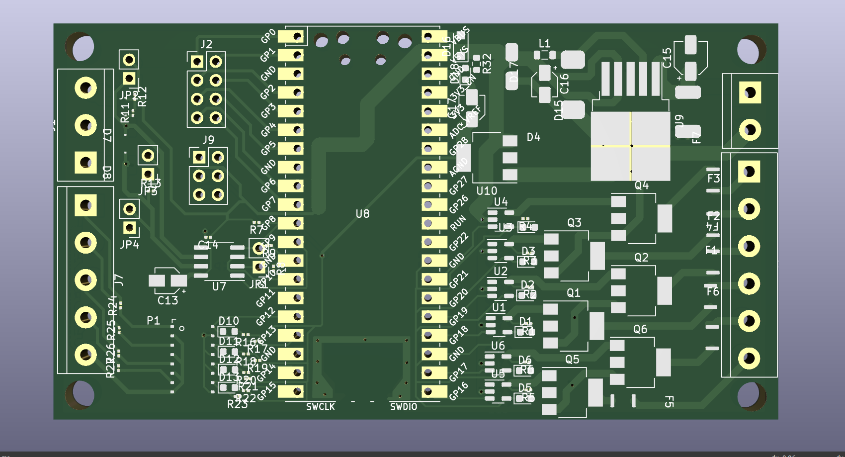

This project was made entirely with Kicad.
Download external dependencies with:
git submodule update --initI'd believe the project should be set automatically since I've taken care to include all libraries as "Project" libraries, not "Global". In any case, if that fails you may follow the steps detailed here to setup any symbol, footprint and 3D model libraries that may be needed to work or visualize the PIAA.
After initializing git submodules with external symbol and footprint libraries (with git submodule update --init) follow the symbol installation instructions at this link and use the footprint in the folder [RP-Pico Libraries](./submodules/KiCad-RP-Pico/RP-Pico Libraries).
Setup piaalib symbol and footprint libraries. They are located under design/lib/piaalib.
The steps to adding these libraries are the same as with the RP-Pico libraries.
| Qty | Value | Footprint | References |
|---|---|---|---|
| 7 | LED RED | LED_SMD:LED_0603_1608Metric | D1, D2, D3, D4, D5, D6, D18 |
| 6 | 100k | Resistor_SMD:R_0201_0603Metric | R10, R11, R17, R19, R21, R23 |
| 6 | 100nF | Capacitor_SMD:C_0805_2012Metric | C7, C8, C9, C10, C11, C12 |
| 6 | 1uF | Capacitor_SMD:C_0805_2012Metric | C1, C2, C3, C4, C5, C6 |
| 6 | 330 | Resistor_SMD:R_0201_0603Metric | R1, R2, R3, R4, R5, R6 |
| 6 | FQT13N06L | Package_TO_SOT_SMD:SOT-223 | Q1, Q2, Q3, Q4, Q5, Q6 |
| 6 | MCP1416 | Package_TO_SOT_SMD:SOT-23-5 | U1, U2, U3, U4, U5, U6 |
| 6 | PTS12066V100 | piaalib:PTS12066V100 | F1, F2, F3, F4, F5, F6 |
| 4 | 2.2k | Resistor_SMD:R_0201_0603Metric | R16, R18, R20, R22 |
| 4 | 3.3k | Resistor_SMD:R_0201_0603Metric | R24, R25, R26, R27 |
| 4 | 4.7k | Resistor_SMD:R_0201_0603Metric | R28, R29, R30, R31 |
| 4 | LED YL | LED_SMD:LED_0603_1608Metric | D10, D11, D12, D13 |
| 4 | jumper | Connector_PinHeader_2.54mm:PinHeader_1x02_P2.54mm_Vertical | JP1, JP2, JP3, JP4 |
| 3 | 4k7 | Resistor_SMD:R_0201_0603Metric | R7, R8, R9 |
| 3 | PSD12C | piaalib:SOD-323 | D7, D8, D9 |
| 2 | 680 | Resistor_SMD:R_0201_0603Metric | R12, R14 |
| 2 | USMF020 | piaalib:USMF020 | PS1, PS2 |
| 1 | 100 @ 1/2W | Resistor_SMD:R_1206_3216Metric | R15 |
| 1 | 100nF | Capacitor_SMD:C_0201_0603Metric | C14 |
| 1 | 10uF | Capacitor_SMD:CP_Elec_3x5.4 | C17 |
| 1 | 10uF/6V3 | Capacitor_SMD:CP_Elec_3x5.3 | C13 |
| 1 | 120 | Resistor_SMD:R_0201_0603Metric | R13 |
| 1 | 1k | Resistor_SMD:R_0603_1608Metric | R32 |
| 1 | 330uF | Capacitor_SMD:CP_Elec_3x5.4 | C16 |
| 1 | 470uF | Capacitor_SMD:CP_Elec_4x3 | C15 |
| 1 | 47uH | Inductor_SMD:L_0805_2012Metric | L1 |
| 1 | B540C-13-F | piaalib:B540C-13-F | D15 |
| 1 | Conn_01x06_Female | Connector_PinHeader_2.54mm:PinHeader_2x03_P2.54mm_Vertical | J9 |
| 1 | Conn_02x04_Counter_Clockwise | Connector_PinHeader_2.54mm:PinHeader_2x04_P2.54mm_Vertical | J2 |
| 1 | LM2596S-5 | Package_TO_SOT_SMD:TO-263-5_TabPin3 | U9 |
| 1 | MAX3072E | Package_SO:SOIC-8_3.9x4.9mm_P1.27mm | U7 |
| 1 | MURS360T3G | piaalib:MURS360T3G | D14 |
| 1 | NCP1117-3.3_SOT223 | Package_TO_SOT_SMD:SOT-223-3_TabPin2 | U10 |
| 1 | PMEG3020EH | Diode_SMD:D_SOD-123F | D16 |
| 1 | PS2805-4 | piaalib:SSOP-16_0.5x0.4mm_pitch1.27mm | P1 |
| 1 | PTS18126V300 | piaalib:PTS18126V300 | F7 |
| 1 | Pico | MCU_RaspberryPi_and_Boards:RPi_Pico_SMD_TH | U8 |
| 1 | SMAZ5V6 | piaalib:SMAZ5V6 | D17 |
| 1 | Screw_Terminal_01x02 | TerminalBlock:TerminalBlock_bornier-2_P5.08mm | J8 |
| 1 | Screw_Terminal_01x03 | TerminalBlock:TerminalBlock_bornier-3_P5.08mm | J1 |
| 1 | Screw_Terminal_01x05 | TerminalBlock:TerminalBlock_bornier-5_P5.08mm | J7 |
| 1 | Screw_Terminal_01x06 | TerminalBlock:TerminalBlock_bornier-6_P5.08mm | J6 |
It measures 98.6 × 53.8 mm and has 2 copper layers, 1.6 mm thick.
104 parts, built around the MAX3072EESA+, MCP1416-E/OT, LM2596S-5.0 and FQT13N06L-VB. The full list of its parts is on this page, with links to each part's symbol and footprint where PCBKit's library has them.
From the soypat/piaa repository on GitHub, at the commit this page was made from: the board is design/piaa/piaa.kicad_pcb and its schematic design/piaa/piaa.kicad_sch. PCBKit opens the board in the browser, with nothing to install.
Its repository publishes it under the GPL-2.0 licence: you may reuse it on that licence's terms (keep the author's notice, and for a copyleft licence share your changes alike).

ciaa/Ponchos
El poncho consta de elemento digitales y analógicos tales como: potenciómetro, buzzer, UART/RS-232, LCD 16x2, teclado matricial 4x3, y pinout para comunicaciones varias y pines de propósito general.

gonblas/blitzcrank
Blitzcrank es un prototipo de garra robótica móvil controlada manualmente, capaz de desplazarse en los ejes X e Y mediante rieles y de realizar movimientos de subida, bajada, apertura y cierre para la manipulación de…

brengi/CESE-PCB
Curso de Diseño de Circuitos Impresos de la Carrera de Especialización en Sistemas Embebidos

Cadburies/SisuAssistant
Sailing yacht Sisu: Home Assistant + ESPHome Marine Board (alternator regulation, tanks) + MQTT kernel, Signal K/Grafana/InfluxDB on a NAS, and Sisu Nav chart & weather-routing cockpit.


