2 layers103 × 30.5 mm
 sourcebots/microswitch-hw
Design for mounting microswitch cicuits on 2020 aluminium extrusion
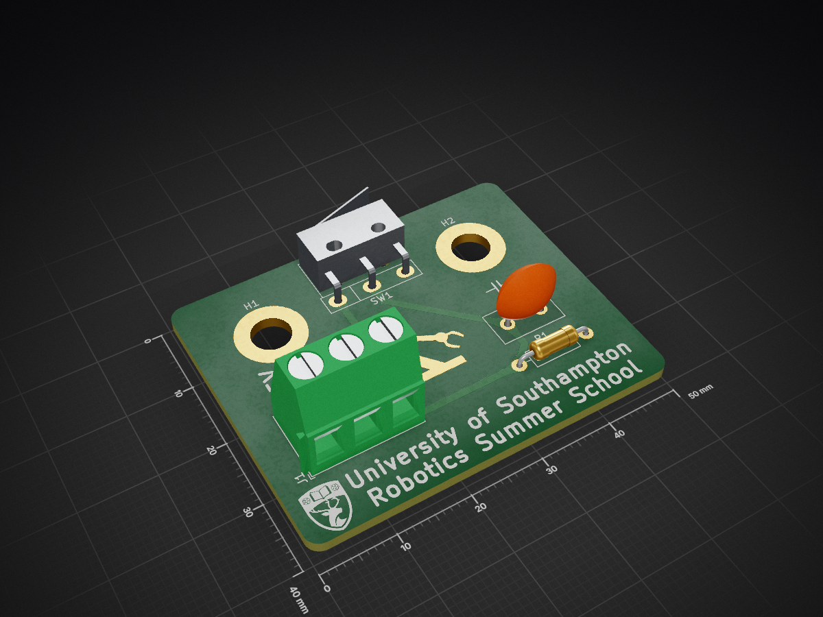
Switch pcb is an open-source printed circuit board by sourcebots, from the sourcebots/microswitch-hw repository on GitHub. It is a 2-layer board of 50 × 40 mm with 9 parts on 6 nets, routed with 8 tracks and 0 vias.
Its parts include 1 capacitor, 1 resistor, 1 connector and 1 switch.
As part of the Smallpeice summer school, students create sensors to mount on their robots. Previously, this has been done using breadboards and veroboard. This suffered from issues with fitting the microswitch pins into the breadboards and mounting the board to the robot.
As such, this PCB is designed to be a simple breakout board for a microswitch. It has footprints for a microswitch, debouncing circuitry and a 3-pin screw terminal to connect to the board. The board is designed to be mounted on 2020 aluminium extrusion chassis with M5 screws.


| Qty | Value | Footprint | References |
|---|---|---|---|
| 2 | MountingHole_Pad | MountingHole:MountingHole_5.3mm_M5_ISO7380_Pad | H1, H2 |
| 1 | 3x5mm | TerminalBlock_Phoenix:TerminalBlock_Phoenix_MKDS-1,5-3_1x03_P5.00mm_Horizontal | J1 |
| 1 | ??? | Resistor_THT:R_Axial_DIN0207_L6.3mm_D2.5mm_P10.16mm_Horizontal | R1 |
| 1 | ??? | Capacitor_THT:C_Disc_D9.0mm_W5.0mm_P5.00mm | C2 |
| 1 | LOGO | switch_pcb:SRO-arm-copper | G*** |
| 1 | LOGO | switch_pcb:SRO-arm | G*** |
| 1 | LOGO | switch_pcb:UoS | G*** |
| 1 | Microswitch | switch_pcb:TC-5610D2-T | SW1 |
It measures 50 × 40 mm and has 2 copper layers, 1.6 mm thick.
9 parts. The full list of its parts is on this page, with links to each part's symbol and footprint where PCBKit's library has them.
From the sourcebots/microswitch-hw repository on GitHub, at the commit this page was made from: the board is switch_pcb.kicad_pcb and its schematic switch_pcb.kicad_sch. PCBKit opens the board in the browser, with nothing to install.
Its repository states no licence, so its author keeps all rights: ask sourcebots before reusing the design.


FrameworkComputer/ExpansionCards
Reference designs and documentation to create Expansion Cards for the Framework Laptop

VoronDesign/Voron-Hardware
Cool Hardware designed by the Voron Design group

hackclub/OnBoard
💡 Join 1,000 teenagers and make your first PCB with a $100 grant!


adamws/kicad-kbplacer
KiCad plugin for automatic keyboard's key placement and routing