
2 layers85 × 67 mm
Gaggimate
dulerabbit/GaggiBre-legacy
This is GaggiBre! a fork of Gaggimate with Manual Brew Control and Adaptive Mode. Made by Dule Rabbit
113 parts8

I made this so my lazyaahh doesnt have to walk upto switches
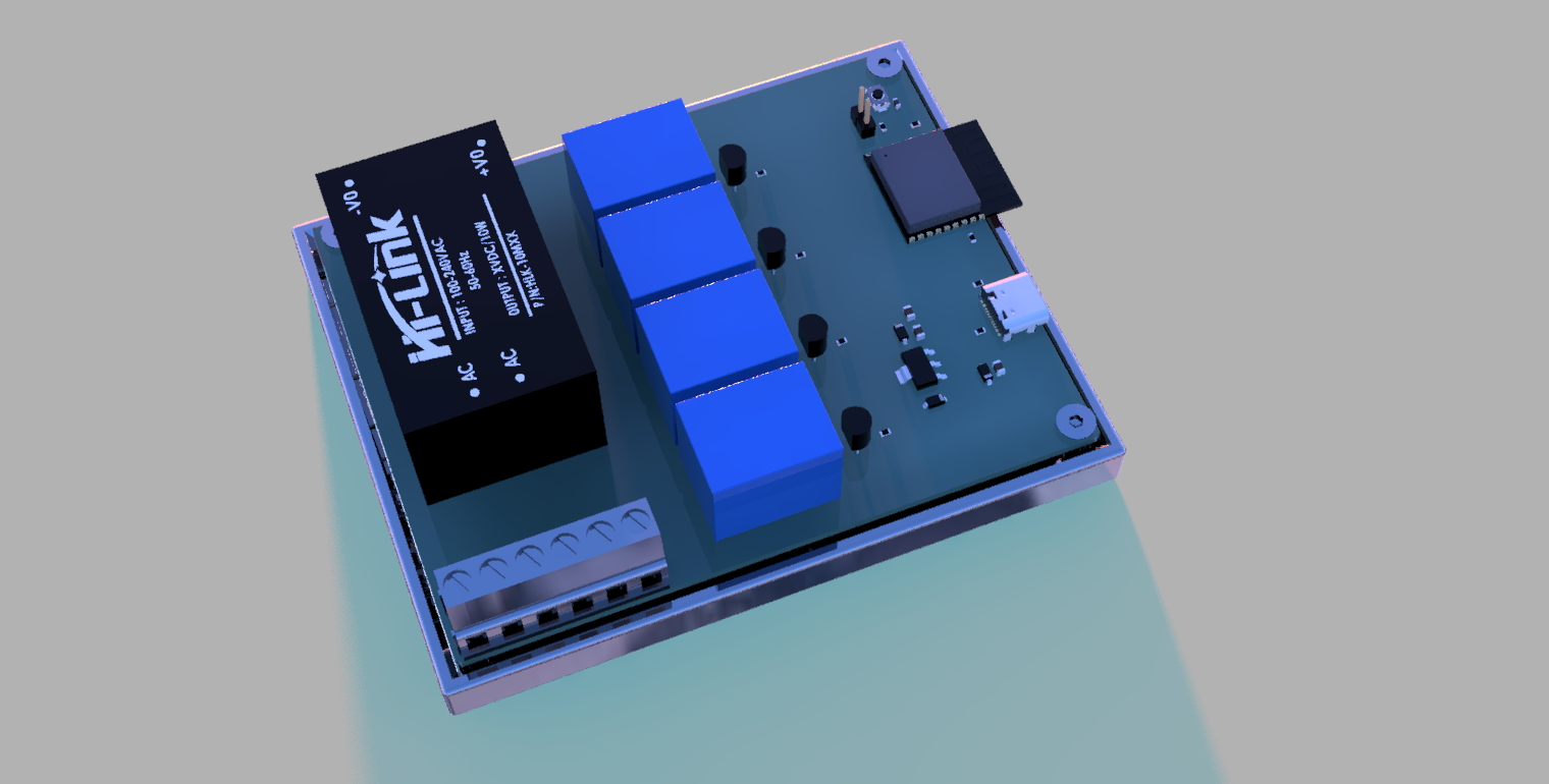
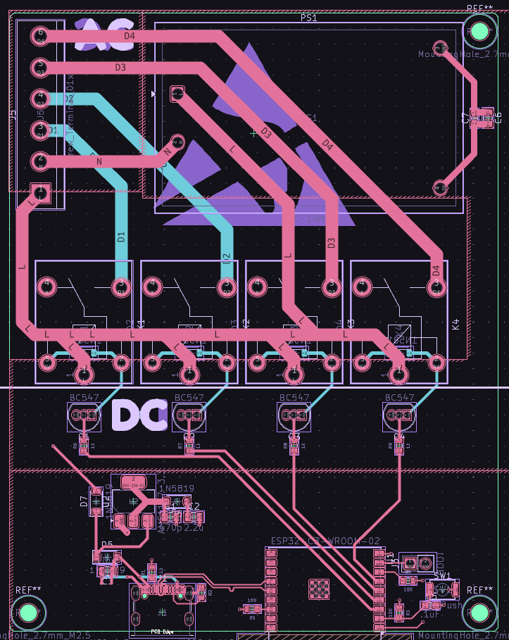
Room is an open-source printed circuit board by souptik-samanta, from the souptik-samanta/LazyController repository on GitHub. It is a 4-layer board of 79 × 100 mm with 56 parts on 45 nets, routed with 227 tracks and 16 vias.
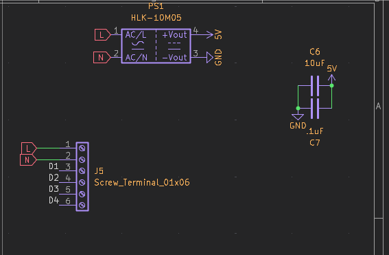
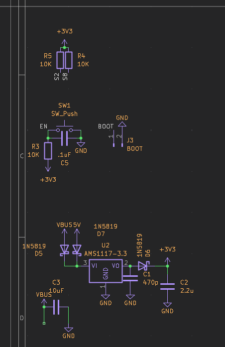
It is built around the HLK-10M05, AMS1117-3.3 and BC547. Its parts include 11 resistors, 7 diodes, 5 capacitors, 4 transistors and 4 switches. It belongs with the ESP32 boards of this library.


A compact WiFi-enabled relay controller built on a custom PCB. Flip switches, trigger appliances, and automate stuff — all from your phone or browser. No getting up required.
BUILD
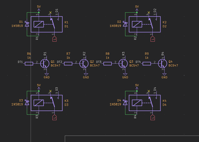
LazyController is an IoT relay board designed around an ESP-based microcontroller. It exposes relay outputs over WiFi, letting you remotely toggle lights, fans, pumps, or anything else you'd rather not walk over to.
LazyController/
├── Cad/          # Enclosure and assembly CAD files
├── Code/         # Firmware source (code.ino)
├── lib/          # README images/assets
├── Pcb/          # KiCad project files (schematic + PCB)
├── production/   # Manufacturing outputs (BOM, positions, netlist, backups)
└── README.mdThe board was designed with simplicity in mind — power in, relay out, WiFi in the middle.
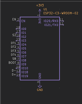
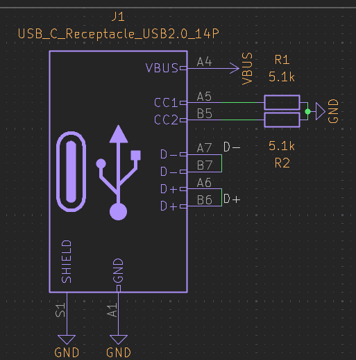
PCB layout and schematic are in the
Pcb/folder.
Gerbers for direct upload to your fab of choice are inproduction/.
Make sure you have the Arduino IDE or PlatformIO installed.
https://espressif.github.io/arduino-esp32/package_esp32_index.jsonESPWiFi (or WiFi for ESP32)ESPAsyncWebServer (recommended)const char* ssid = "your_network";
const char* password = "your_password";115200 baud — it'll print the device IP once connectedPower the controller → relays get activated → each relay switches its connected load.Relay outputs are SPDT — connect your load between COM and NO (normally open) for off-by-default behaviour.
If switching mains voltage (120V/230V AC), make sure you take appropriate safety precautions.
Once flashed and powered:
GET /relay/1/on
GET /relay/1/off| NAME | DESC | QUAN | PRICE (USD) | PRICE TOT | LINK |
|---|---|---|---|---|---|
| AC DC HLK 10M05 | 1 | 3 | 3 | Link | |
| 6 Pin 5.08mm Pitch Pluggable Screw Terminal Block | 1 | 1 | 1 | Link | |
| RELAY | 4 | 1 | 4 | Link | |
| pcb | 23 | 1 | 23 | ||
| LCSC | |||||
| CC0805JRNPO9BN471 | Description | 100 | 0.0074 | 0.74 | Link |
| CL21A225KBQNNNE | 470pF ±5% 50V Ceramic Capacitor NP0 0805 | 10 | 0.0176 | 0.176 | Link |
| GRM21BR61H106KE43L | 2.2uF ±10% 50V Ceramic Capacitor X5R 0805 | 10 | 0.0723 | 0.723 | Link |
| CC0603KRX7R9BB104 | 10uF ±10% 50V Ceramic Capacitor X5R 0805 | 100 | 0.0028 | 0.28 | Link |
| 1N5819W | 100nF ±10% 50V Ceramic Capacitor X7R 0603 | 100 | 0.0072 | 0.72 | Link |
| TYPE-C 16PIN 2MD(073) | Diode Independent 40V 350mA Surface Mount SOD-123 | 20 | 0.0617 | 1.234 | Link |
| BC547 | USB-C (USB TYPE-C) Receptacle Connector 16 Position Surface Mount, Right Angle | 20 | 0.0302 | 0.604 | Link |
| FRC0603F5101TS | Bipolar (BJT) Transistor NPN 45V 0.1A 150MHz 625mW Through Hole TO-92 | 100 | 0.0012 | 0.12 | Link |
| RC0603FR-0710KL | 5.1kΩ ±1% 100mW 0603 Thick Film Resistor | 100 | 0.0013 | 0.13 | Link |
| RC0603FR-071KL | 100mW 10kΩ 75V Thick Film Resistor ±100ppm/℃ ±1% 0603 Chip Resistor - Surface Mount RoHS | 100 | 0.0013 | 0.13 | Link |
| SKRKAEE020 | 100mW 1kΩ 75V Thick Film Resistor ±100ppm/℃ ±1% 0603 Chip Resistor - Surface Mount RoHS | 5 | 0.1309 | 0.6545 | Link |
| ESP32-C3-WROOM-02-N4 | Tactile Switch SPST 2mm 3.9mm x 2.9mm Surface Mount | 1 | 3.0674 | 3.0674 | Link |
| AMS1117-3.3 | 2.4GHz ESP32-C3 Chip On-board PCB Antenna -105dBm VFQFN-32-EP RF Transceiver Modules and Modems RoHS | 5 | 0.2259 | 1.1295 | Link |
| 3.3V 15V Positive Fixed SOT-223 Voltage Regulators - Linear, Low Drop Out (LDO) Regulators RoHS | |||||
| TOTAL | 50.7084 |
| Qty | Value | Footprint | References |
|---|---|---|---|
| 7 | 1N5819 | Diode_SMD:D_SOD-123 | D1, D2, D3, D4, D5, D6, D7 |
| 6 | MountingHole | MountingHole:MountingHole_2.5mm | H1, H2, H3, H4, H5, H6 |
| 5 | LED | LED_SMD:LED_0805_2012Metric_Pad1.15x1.40mm_HandSolder | DL1, DL2, DL3, DL4, DL5 |
| 4 | 1k | PCM_SparkFun-Resistor:R_0603_1608Metric | R6, R7, R8, R9 |
| 4 | BC547 | Package_TO_SOT_THT:TO-92_Inline | Q1, Q2, Q3, Q4 |
| 3 | 220 | PCM_SparkFun-Resistor:R_0603_1608Metric | R3, R4, R5 |
| 2 | 10uF | Capacitor_SMD:C_0805_2012Metric | C3, C6 |
| 2 | 330 | PCM_SparkFun-Resistor:R_0603_1608Metric | R10, R11 |
| 2 | 5.1k | PCM_SparkFun-Resistor:R_0603_1608Metric | R1, R2 |
| 1 | .1uF | Capacitor_SMD:C_0603_1608Metric_Pad1.08x0.95mm_HandSolder | C7 |
| 1 | 2.2u | Capacitor_SMD:C_0805_2012Metric | C2 |
| 1 | 470p | Capacitor_SMD:C_0805_2012Metric | C1 |
| 1 | AMS1117-3.3 | Package_TO_SOT_SMD:SOT-223-3_TabPin2 | U2 |
| 1 | Conn_01x05_Pin | Connector_PinHeader_2.54mm:PinHeader_1x05_P2.54mm_Vertical | J2 |
| 1 | D1 | Relay_THT:Relay_SPDT_SANYOU_SRD_Series_Form_C | K1 |
| 1 | D2 | Relay_THT:Relay_SPDT_SANYOU_SRD_Series_Form_C | K2 |
| 1 | D3 | Relay_THT:Relay_SPDT_SANYOU_SRD_Series_Form_C | K3 |
| 1 | D4 | Relay_THT:Relay_SPDT_SANYOU_SRD_Series_Form_C | K4 |
| 1 | G*** | kibuzzard-69C64D69 | kibuzzard-69C64D69 |
| 1 | G*** | kibuzzard-69B63945 | kibuzzard-69B63945 |
| 1 | G*** | kibuzzard-69B63969 | kibuzzard-69B63969 |
| 1 | HLK-10M05 | Converter_ACDC:Converter_ACDC_Hi-Link_HLK-10Mxx | PS1 |
| 1 | LOGO | LOGO | G*** |
| 1 | Screw_Terminal_01x06 | TerminalBlock:TerminalBlock_bornier-6_P5.08mm | J5 |
| 1 | USB_C_Receptacle_USB2.0_14P | Connector_USB:USB_C_Receptacle_GCT_USB4105-xx-A_16P_TopMnt_Horizontal | J1 |
| 1 | XIAO-ESP32-S3-DIP | Seeed Studio XIAO Series Library:XIAO-ESP32S3-DIP | U3 |
The 52 most common of 56 parts.
It measures 79 × 100 mm and has 4 copper layers, 1.6 mm thick.
56 parts, built around the HLK-10M05, AMS1117-3.3 and BC547. The full list of its parts is on this page, with links to each part's symbol and footprint where PCBKit's library has them.
From the souptik-samanta/LazyController repository on GitHub, at the commit this page was made from: the board is Pcb/room.kicad_pcb and its schematic Pcb/room.kicad_sch. PCBKit opens the board in the browser, with nothing to install.
Its repository states no licence, so its author keeps all rights: ask souptik-samanta before reusing the design.
dulerabbit/GaggiBre-legacy
This is GaggiBre! a fork of Gaggimate with Manual Brew Control and Adaptive Mode. Made by Dule Rabbit

AlterMundi-MonitoreoyControl/Proyecto-Incubadora
Is an innovative project aimed at enhancing the efficiency and productivity of poultry incubators in family farming.

akashh218/ESP32-8-Channel-Smart-Switch-PCB
ESP32-based 8-channel smart switch PCB for wireless control of multiple electrical loads, featuring relay interfaces and a compact PCB design.


AntoJijoKICKU/Smart_PLUG
This is Untested version of Hardware Double check your guts before take this as reference


JamieKaiRemkes/ESPresence
Presence sensor build with LD2410 24GHz mmWave sensor using ESPhome
