2 layers97.2 × 59.1 mm
ArmLEDsPrototype
hackclub/OnBoard
💡 Join 1,000 teenagers and make your first PCB with a $100 grant!
35 parts915

 somhi/MiSTdon5
MiST addon for converting any FPGA into a MiST "compatible" platform
MiSTdon is an open-source printed circuit board by somhi, from the somhi/MiSTdon repository on GitHub. It is a 2-layer board of 70 × 70 mm with 35 parts on 64 nets, routed with 466 tracks and 33 vias.
Its parts include 12 resistors, 12 connectors, 3 switches and 1 diode. It belongs with the fPGA and programmable logic boards of this library.
MiSTdon is an addon for any FPGA to be nearly compatible with the MiST FPGA platform.
Project has been developed with KiCAD 6.0.11.
STATUS (17/03/23): first PCB assembled. After first testing, all seems to work well. Some changes will be introduced in next revision (see TODO list below).
STATUS (25/02/23): prototype design work finished. v0.7 gerbers sent to JLCPCB for manufacturing.
Acknowledgements and thanks for help go to Jepalza, Volton and Manuferhi.
See main repository Readme for materials list
Better do not connect/disconnect interfaces while the board is powered
Read jumper selection below.
Defaults are OPEN (jumper not placed or not soldered) and CLOSED (jumper placed or soldered)
JP1 jumper closed connects 5V to USB VBus (make sure before place jumper to cut the R222 track in MAX3421E USB Mini shield). In case of doubt do not place this jumper, so not all USB peripherals will work at 3V3 which is applied to VBUS when jumper is disconnected.
JP2 solder jumper. Central position with GND for SD Cards without this signal. Central position with CD for Digilent Pmod SD card. In case of doubt solder central position and GND.
JP3 place jumper in RST pins (leave GND pin unconnected).
Connect wires from 5V and GND pins of P7 header (AT91SAM7S256 board) to J6 header 5V and GND pins.
Connect wire from 5V FPGA pin to J6 header 5V pin.
Connect wire from RST pin 3 of JTAG header (AT91SAM7S256 board) to J6 header NRST pin.
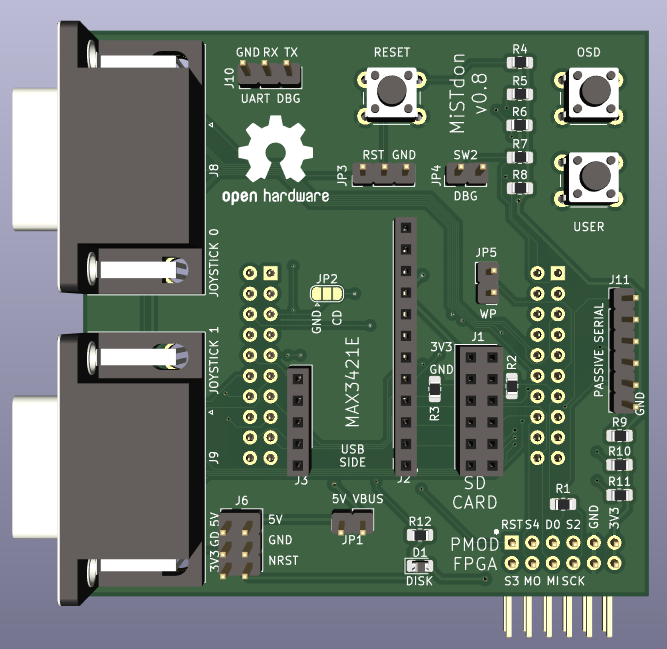
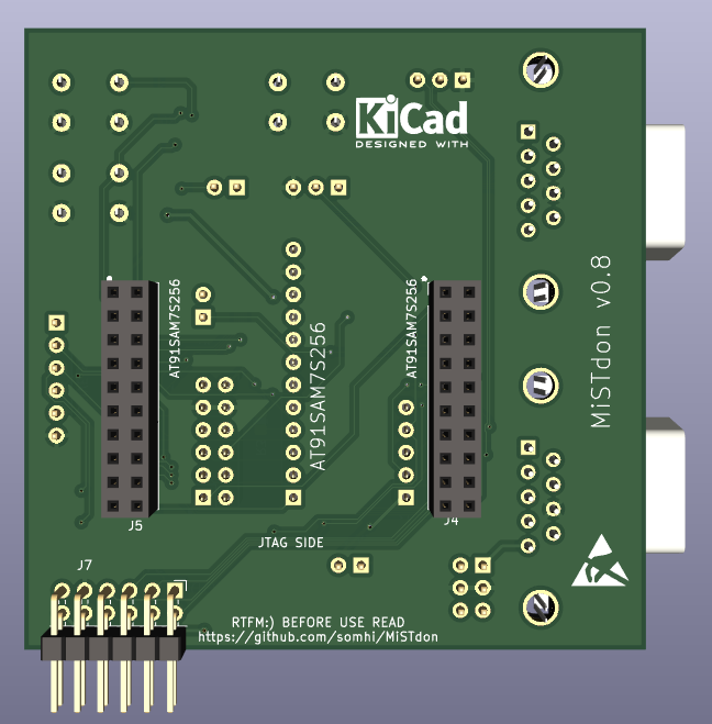
v0.7 finished prototype desing. Gerber sent to JLCPCB for manufacturing
v0.8 see changes below:
| Qty | Value | Footprint | References |
|---|---|---|---|
| 4 | 10k | Resistor_SMD:R_0805_2012Metric_Pad1.20x1.40mm_HandSolder | R4, R9, R10, R11 |
| 4 | 4k7 | Resistor_SMD:R_0805_2012Metric_Pad1.20x1.40mm_HandSolder | R5, R6, R7, R8 |
| 3 | 47 | Resistor_SMD:R_0805_2012Metric_Pad1.20x1.40mm_HandSolder | R1, R2, R3 |
| 3 | Conn_01x02 | Connector_PinHeader_2.54mm:PinHeader_1x02_P2.54mm_Vertical | JP1, JP4, JP5 |
| 3 | SW_Push | Button_Switch_THT:SW_PUSH_6mm_H5mm | SW1, SW3, SW4 |
| 2 | Conn_01x03 | Connector_PinHeader_2.54mm:PinHeader_1x03_P2.54mm_Vertical | J10, JP3 |
| 2 | Conn_02x10_Odd_Even | Connector_PinSocket_2.54mm:PinSocket_2x10_P2.54mm_Vertical | J4, J5 |
| 2 | DB9_Male | Connector_Dsub:DSUB-9_Male_Horizontal_P2.77x2.84mm_EdgePinOffset9.90mm_Housed_MountingHolesOffset11.32mm | J8, J9 |
| 1 | 220 | Resistor_SMD:R_0805_2012Metric_Pad1.20x1.40mm_HandSolder | R12 |
| 1 | Conn_01x05 | Connector_PinSocket_2.54mm:PinSocket_1x05_P2.54mm_Vertical | J3 |
| 1 | Conn_01x06 | Connector_PinHeader_2.54mm:PinHeader_1x06_P2.54mm_Vertical | J11 |
| 1 | Conn_01x12 | Connector_PinSocket_2.54mm:PinSocket_1x12_P2.54mm_Vertical | J2 |
| 1 | Conn_02x03_Odd_Even | Connector_PinHeader_2.54mm:PinHeader_2x03_P2.54mm_Vertical | J6 |
| 1 | Conn_02x06_Top_Bottom | libraries:Pmod_2x06_P2.54mm_Vertical_2 | J1 |
| 1 | Conn_02x06_Top_Bottom | libraries:PMOD_Female_Horizontal_2 | J7 |
| 1 | ESD-Logo_6.6x6mm_SilkScreen | Symbol:ESD-Logo_6.6x6mm_SilkScreen | LO4 |
| 1 | LED | Diode_SMD:D_0805_2012Metric_Pad1.15x1.40mm_HandSolder | D1 |
| 1 | OSHW-Logo2_14.6x12mm_SilkScreen | Symbol:OSHW-Logo2_14.6x12mm_SilkScreen | LO2 |
| 1 | SolderJumper_3_Open | Jumper:SolderJumper-3_P1.3mm_Open_RoundedPad1.0x1.5mm | JP2 |
The 34 most common of 35 parts.
It measures 70 × 70 mm and has 2 copper layers, 1.6 mm thick.
35 parts. The full list of its parts is on this page, with links to each part's symbol and footprint where PCBKit's library has them.
From the somhi/MiSTdon repository on GitHub, at the commit this page was made from: the board is MiSTdon.kicad/MiSTdon.kicad_pcb and its schematic MiSTdon.kicad/MiSTdon.kicad_sch. PCBKit opens the board in the browser, with nothing to install.
Its repository states no licence, so its author keeps all rights: ask somhi before reusing the design.
hackclub/OnBoard
💡 Join 1,000 teenagers and make your first PCB with a $100 grant!


ozel/DIY_particle_detector
A mobile low-cost spectrometer for measuring radioactivity and the energy of ionising radiation like alpha particles and electrons

Seeed-Studio/OSHW-reCamera-Series
reCamera is a series of open-source AI cameras.


