

2 layers75 × 40 mm
Lcddriver
ansemjo/chronovfd
hardware project for a clock around a russian ivl2-5/7 vfd and an esp32-wroom module
25 parts13CERN-OHL-P-2.0

A 4-digit 7-segment display module based on the NXP PCF8562 driver IC
Lcd-7seg is an open-source printed circuit board by SomeInterestingUserName, from the SomeInterestingUserName/lcd-7seg repository on GitHub, published under the MIT licence. It is a 2-layer board of 66 × 45.1 mm with 21 parts on 57 nets, routed with 661 tracks and 155 vias.
It is built around the PCF8562TT/2 and LCD-S401C52TR. Its parts include 4 capacitors, 2 resistors, 1 IC and 1 connector. It belongs with the lEDs and displays boards of this library.
A 4-digit 7-segment display module based on the NXP PCF8562 driver IC. The PCB fits a Lumex LCD-S401C52TR display. With the exception of Backplanes 2-4, all other pins of the PCF8562 are broken out to headers or jumpers to allow for evaluation of advanced features.
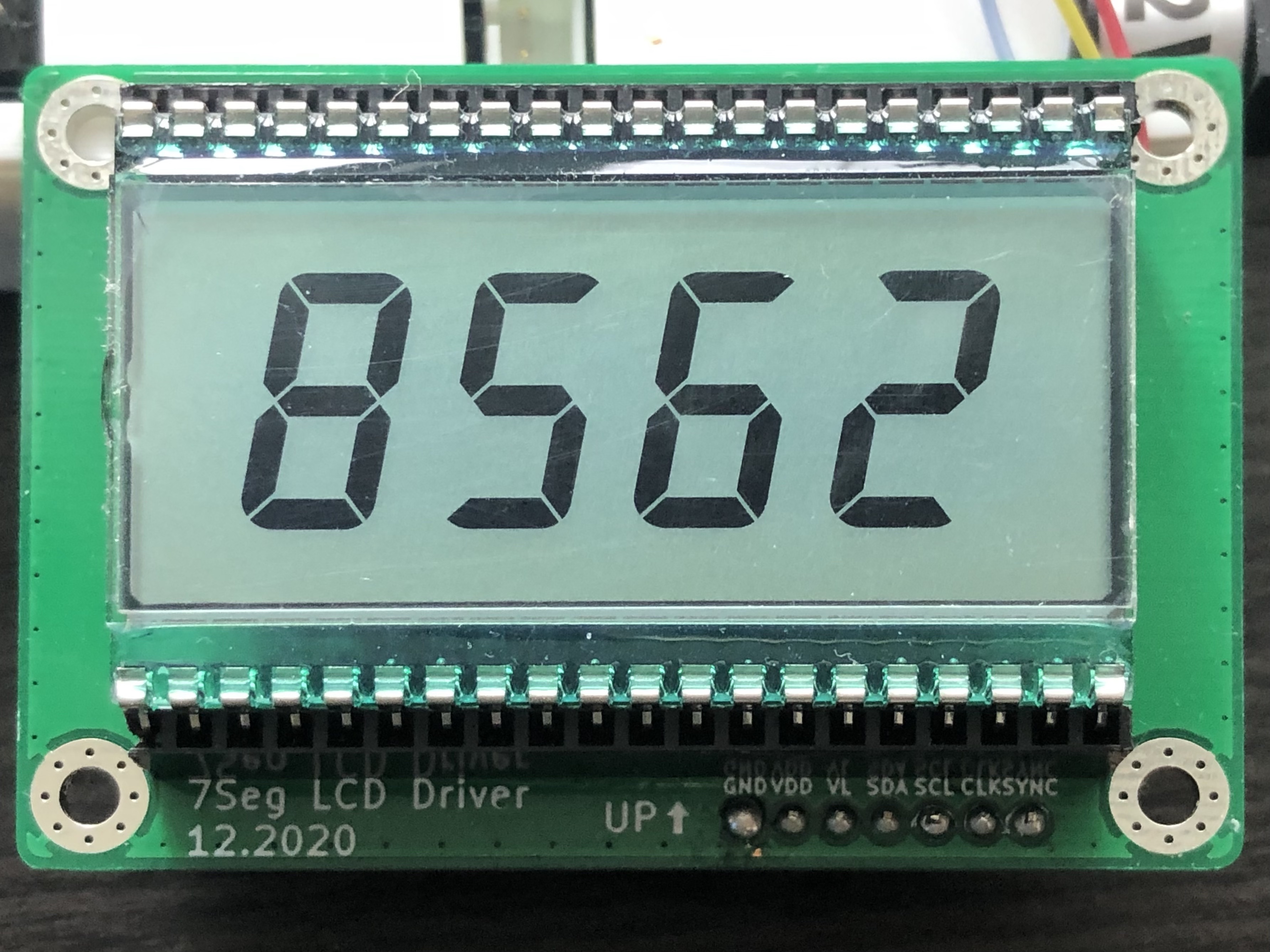 Note: The NXP datasheet currently lists the PCF8562 as "Not Recommended for New Designs". The PCF85162 (note the additional "1") is a drop-in replacement for this part. However, the PCF8562 (without the "1") is still widely available, and in fact appears to be available in larger quantities at the moment (as of January 2021).
A0: 0A1: 0A2: 0I2C ADDR: 0x70OSC: INTVLCD: VDD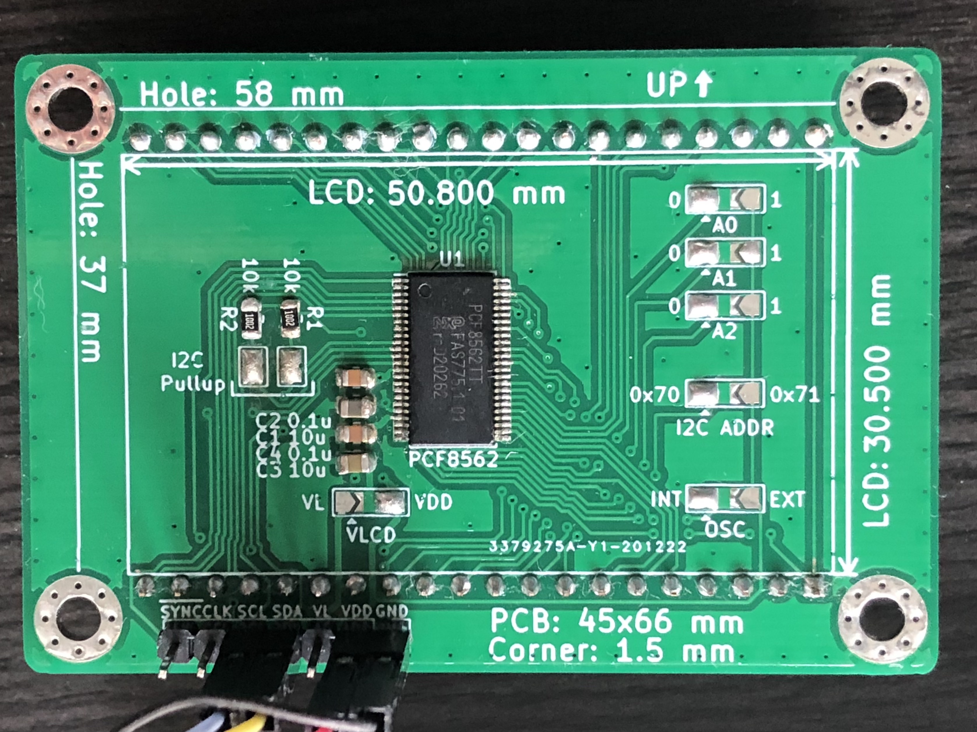
| Qty | Value | Footprint | References |
|---|---|---|---|
| 6 | SolderJumper_3_Open | Jumper:SolderJumper-3_P2.0mm_Open_TrianglePad1.0x1.5mm | JP3, JP4, JP5, JP6, JP7, JP8 |
| 4 | MountingHole_Pad | MountingHole:MountingHole_3.2mm_M3_Pad_Via | H1, H2, H3, H4 |
| 2 | 0.1u | Capacitor_SMD:C_0805_2012Metric | C2, C4 |
| 2 | 10k | Resistor_SMD:R_0805_2012Metric | R1, R2 |
| 2 | 10u | Capacitor_SMD:C_0805_2012Metric | C1, C3 |
| 2 | SolderJumper_2_Open | Jumper:SolderJumper-2_P1.3mm_Open_TrianglePad1.0x1.5mm | JP1, JP2 |
| 1 | Conn_01x07 | Connector_PinHeader_2.54mm:PinHeader_1x07_P2.54mm_Vertical | J1 |
| 1 | LCD-S401C52TR | custom_components:S401C52TR | DISP1 |
| 1 | PCF8562 | Package_SO:TSSOP-48_6.1x12.5mm_P0.5mm | U1 |
ansemjo/chronovfd
hardware project for a clock around a russian ivl2-5/7 vfd and an esp32-wroom module

gusmanb/logicanalyzer
24 channel, 100Msps logic analyzer hardware and software

mntmn/amiga2000-gfxcard
MNT VA2000, an Open Source Amiga 2/3/4000 Graphics Card (Zorro II/III), written in Verilog


hackclub/OnBoard
💡 Join 1,000 teenagers and make your first PCB with a $100 grant!

drandyhaas/KiCadRoutingTools
A set of Python/Rust tools to aid routing in KiCad

Arrow-air/project-quiver
Project Quiver documentation, designs, and project artifacts.

It measures 66 × 45.1 mm and has 2 copper layers, 1.6 mm thick.
21 parts, built around the PCF8562TT/2 and LCD-S401C52TR. The full list of its parts is on this page, with links to each part's symbol and footprint where PCBKit's library has them.
From the SomeInterestingUserName/lcd-7seg repository on GitHub, at the commit this page was made from: the board is hw/LCD7Seg.kicad_pcb and its schematic hw/LCD7Seg.kicad_sch. PCBKit opens the board in the browser, with nothing to install.
Its repository publishes it under the MIT licence: you may reuse it on that licence's terms (keep the author's notice, and for a copyleft licence share your changes alike).