2 layers22 × 38 mm
Basic stepper driver
SolderedElectronics/Basic-stepper-driver-hardware-design
Hardware design, BOM, gerbers and 3D files for Basic-stepper-driver designed by Soldered Electronics.
57 parts1
 SolderedElectronics/Basic-stepper-driver-hardware-design1
Hardware design, BOM, gerbers and 3D files for Basic-stepper-driver designed by Soldered Electronics.
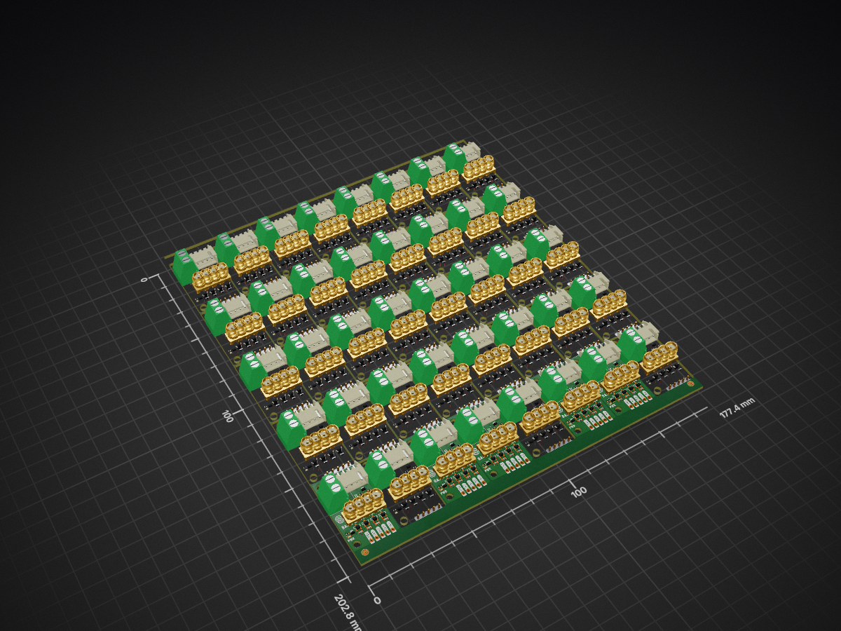
Basic stepper driver is an open-source printed circuit board by SolderedElectronics, from the SolderedElectronics/Basic-stepper-driver-hardware-design repository on GitHub. It is a 2-layer board of 177.4 × 202.8 mm with 2,284 parts on 21 nets, routed with 4,600 tracks and 1,120 vias.
Its parts include 360 resistors, 360 diodes, 160 transistors and 120 switches. It belongs with the robots and motor control boards of this library.
This driver for stepper motor enables control over a stepper motor that does not require more than 800mA of current and works at up to 14V voltage. Except for the driver, it has built-in LED lights that indicate which phase of the motor is currently active. Connecting with microcontroller is easy, and control is directly through the library.
This repository contains all design files for Basic stepper driver, organized as follows:
CAD folder: Contains KiCAD design files, including:
OUTPUTS folder: Includes all production-ready files, such as:
.step file of the boardRefer to the Change Log in the CAD folder for details about updates between versions.
Beyond the repository, explore the following resources:

The Soldered Verify system ensures every board you purchase from Soldered is fully functional. It also provides access to exclusive test data for your product. To get started, find the unique Soldered Verify ID on your product's packaging and enter the ID on the Soldered Verify page to access test results and additional product details.

Soldered Community is your go-to place for technical support. Our engineers track and answer all questions posted there, and it’s a great space for the maker community. Get answers to your questions and solutions for your challenges at Soldered Community.
solde.red is an ultimate URL shortener and information hub. Access it by typing solde.red/ followed by your product SKU, e.g., solde.red/333000, to find getting-started guides, datasheets, open-source hardware and software files, certifications, images, pinouts, and more. Read more about the shortener here.
Contributions are welcome! Here’s how you can get involved:
We encourage community collaboration to make this product even better.

Soldered for Makers specializes in designing and manufacturing electronic products tailored for enthusiasts, ranging from hobbyists to professionals. Our portfolio includes electronic boards, sensors, and actuators that are widely utilized in fields such as microelectronics, mechatronics, robotics, programming, and IoT. Every product we offer is designed in-house and built upon open-source hardware and software platforms. Proudly certified and manufactured within the European Union, our catalog likely includes the product you need for your project.
We complement these products with comprehensive tutorials and manuals, product descriptions, schematics, programming codes, and project examples. Our round-the-clock customer and technical support is available for all our products, irrespective of the sales channel. Soldered’s success and services reflect our maker community’s unwavering trust, for which we are deeply grateful. Join our community and create using Soldered products.
All Soldered open-source hardware (OSH) is under The TAPR Open Hardware License. Read more in the LICENSE file located in this repository.
Disclaimer:
No warranty - all designs in this repository are distributed in the hope that they will be useful, but without any warranty. They are provided "AS IS", therefore without warranty of any kind, either expressed or implied. The entire quality and performance of what you do with the contents of this repository are your responsibility. In no event Soldered Electronics will be liable for your damages, or losses, including any general, special, incidental, or consequential damage arising out of the use or inability to use the contents of this repository.
Thank you for your support from your fellow makers at Soldered Electronics.
Happy Making!
| Qty | Value | Footprint | References |
|---|---|---|---|
| 880 | buzzardLabel | , , , , , , , , , , , , , , , +864 | |
| 200 | 2k2 | e-radionica.com footprinti:0402R | R1, R1, R1, R1, R1, R1, R1, R1, R1, R1, R1, R1, R1, R1, R1, R1 +184 |
| 160 | 1k | e-radionica.com footprinti:0603R | R2, R2, R2, R2, R2, R2, R2, R2, R2, R2, R2, R2, R2, R2, R2, R2 +144 |
| 160 | M4_DIODA | e-radionica.com footprinti:M4_DIODA | D2, D2, D2, D2, D2, D2, D2, D2, D2, D2, D2, D2, D2, D2, D2, D2 +144 |
| 160 | NPN-SOT-23-3 | e-radionica.com footprinti:SOT-23-3 | Q1, Q1, Q1, Q1, Q1, Q1, Q1, Q1, Q1, Q1, Q1, Q1, Q1, Q1, Q1, Q1 +144 |
| 160 | green | e-radionica.com footprinti:0402LED | D3, D3, D3, D3, D3, D3, D3, D3, D3, D3, D3, D3, D3, D3, D3, D3 +144 |
| 80 | HOLE_3.2mm | e-radionica.com footprinti:HOLE_3.2mm | H1, H1, H1, H1, H1, H1, H1, H1, H1, H1, H1, H1, H1, H1, H1, H1 +64 |
| 44 | FIDUCIAL | e-radionica.com footprinti:FIDUCIAL_23 | FD1, FD1, FD1, FD1, FD1, FD1, FD1, FD1, FD1, FD1, FD1, FD1, FD1, FD1, FD1, FD1 +28 |
| 40 | HEADER_MALE_5X1 | e-radionica.com footprinti:HEADER_MALE_5X1 | K2, K2, K2, K2, K2, K2, K2, K2, K2, K2, K2, K2, K2, K2, K2, K2 +24 |
| 40 | JST_XH_5A_CONNECTOR | e-radionica.com footprinti:JST_XH_5A_CONNECTOR | K3, K3, K3, K3, K3, K3, K3, K3, K3, K3, K3, K3, K3, K3, K3, K3 +24 |
| 40 | LOGO | Soldered Graphics:Symbol-Front-Motor | G***, G***, G***, G***, G***, G***, G***, G***, G***, G***, G***, G***, G***, G***, G***, G*** +24 |
| 40 | LOGO | Soldered Graphics:Logo-Back-OSH-3.5mm | G***, G***, G***, G***, G***, G***, G***, G***, G***, G***, G***, G***, G***, G***, G***, G*** +24 |
| 40 | LOGO | Soldered Graphics:Logo-Front-Soldered-4mm | G***, G***, G***, G***, G***, G***, G***, G***, G***, G***, G***, G***, G***, G***, G***, G*** +24 |
| 40 | SMD-JUMPER-CONNECTED_TRACE_SLODERMASK | e-radionica.com footprinti:SMD-JUMPER-CONNECTED_TRACE_SLODERMASK | JP1, JP1, JP1, JP1, JP1, JP1, JP1, JP1, JP1, JP1, JP1, JP1, JP1, JP1, JP1, JP1 +24 |
| 40 | SMD_JUMPER | e-radionica.com footprinti:SMD_JUMPER | JP2, JP2, JP2, JP2, JP2, JP2, JP2, JP2, JP2, JP2, JP2, JP2, JP2, JP2, JP2, JP2 +24 |
| 40 | TERMINAL_KF235-5.0-2P | e-radionica.com footprinti:TERMINAL_KF235-5.0-2P | K1, K1, K1, K1, K1, K1, K1, K1, K1, K1, K1, K1, K1, K1, K1, K1 +24 |
| 40 | purple | e-radionica.com footprinti:0402LED | D1, D1, D1, D1, D1, D1, D1, D1, D1, D1, D1, D1, D1, D1, D1, D1 +24 |
The 2,204 most common of 2,284 parts.
It measures 177.4 × 202.8 mm and has 2 copper layers, 1.6 mm thick.
2,284 parts. The full list of its parts is on this page, with links to each part's symbol and footprint where PCBKit's library has them.
From the SolderedElectronics/Basic-stepper-driver-hardware-design repository on GitHub, at the commit this page was made from: the board is CAD/V1.1.1/PANEL/Basic_stepper_driver.kicad_pcb and its schematic CAD/V1.0.0/Basic_stepper_driver.kicad_sch. PCBKit opens the board in the browser, with nothing to install.
Its repository states no licence, so its author keeps all rights: ask SolderedElectronics before reusing the design.
SolderedElectronics/Basic-stepper-driver-hardware-design
Hardware design, BOM, gerbers and 3D files for Basic-stepper-driver designed by Soldered Electronics.

SolderedElectronics/Basic-stepper-driver-hardware-design
Hardware design, BOM, gerbers and 3D files for Basic-stepper-driver designed by Soldered Electronics.

SolderedElectronics/Display-OLED-I2C-White-0.96-hardware-design
Hardware design, BOM, gerbers and 3D files for Display-OLED-I2C-White-0.96 designed by Soldered Electronics.


SolderedElectronics/Dasduino-CORE-Solder-kit-hardware-design
Hardware design, BOM, gerbers and 3D files for Dasduino-CORE-Solder-kit designed by Soldered Electronics.

Pips801/microbadge
Do you find Minibadges too big? Do you want to go even smaller? Try out the Microbadge! A minibadge can hold 4 of them!

SolderedElectronics/8x8-LED-matrix-Purple-MAX7219-board-hardware-design
Hardware design, BOM, gerbers and 3D files for 8x8-LED-matrix-Purple-MAX7219-board designed by Soldered Electronics.

rusefi/hw_microRusEfi
microRusEfi board for rusEfi ECU

sparkfun/SparkFun_Soft_Power_Switch_Mk2
Documentation, example code, and hardware for the SparkFun Soft Power Switch - JST 2mm.