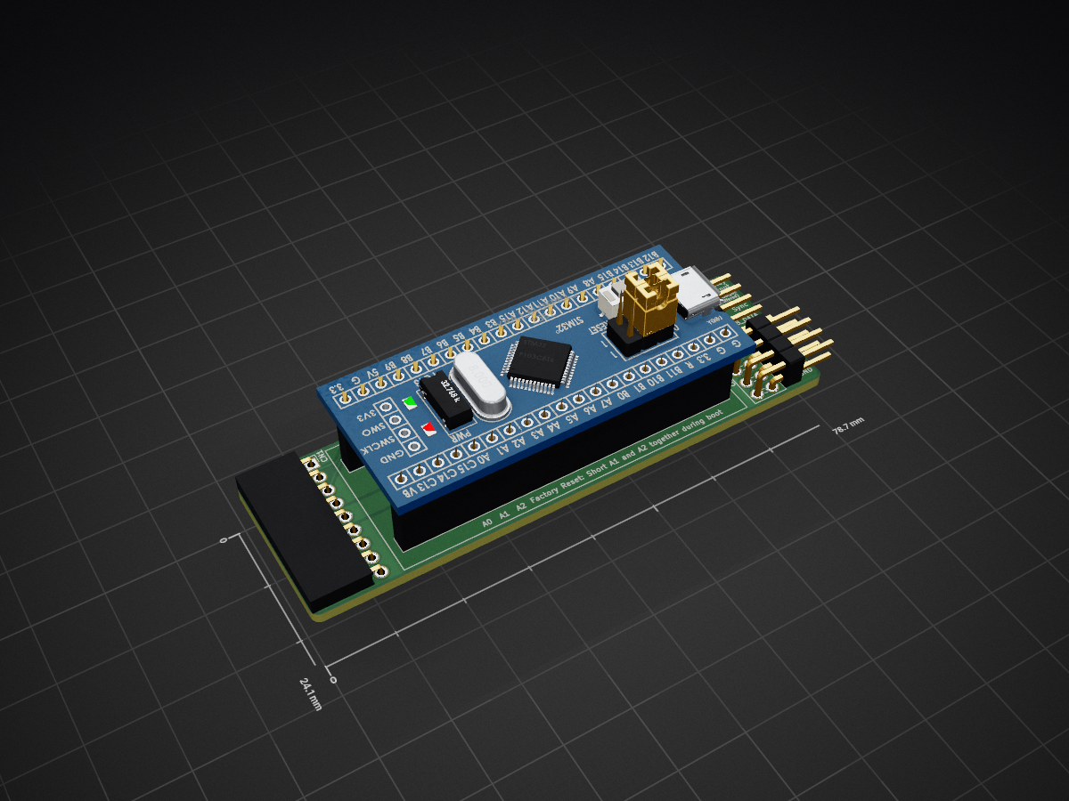
2 layers78.7 × 24.1 mm
 solarmon/FlashFloppy6
FlashFloppy Projects
FF OSD Adapter - Rev 2 is an open-source printed circuit board by solarmon, from the solarmon/FlashFloppy repository on GitHub. It is a 2-layer board of 78.7 × 24.1 mm with 10 parts on 41 nets, routed with 84 tracks and 4 vias.
Its parts include 4 connectors, 3 resistors and 1 IC. It belongs with the interfaces and adapters boards of this library.
This adapter allows a FF OSD Blue Pill to be easily connected to a Gotek and a supported Amiga RGBtoHDMI adapter.
keirf's FF OSD: https://github.com/keirf/FF_OSD
Supported RGBtoHDMI boards: https://github.com/solarmon/RGBtoHDMI
Improvements in Rev 2 include:
Top:

Bottom:

Schematics PDF: https://github.com/solarmon/FlashFloppy/blob/main/FF%20OSD%20Adapter%20-%20Rev%202/FF%20OSD%20Adapter%20-%20Rev%202.pdf
In order to support keyboard integration for the RGBtoHDMI menu buttons , FF OSD needs to be built with support for it. I have forked off the FF OSD files and have provided the example config required to build it with RGBtoHDMI button support - see:
https://github.com/solarmon/FF_OSD
The only change is to add the button code to src/default_config.c:
#if 1
    /* An example for RGBtoHDMI momentary buttons */
    .user_pin_opendrain = U(2) | U(1) | U(0),	/* Set these pins as open drain */
    .user_pin_pushpull  = 0,					/* No buttons as pushpull */
	.user_pin_high		= U(2) | U(1) | U(0),	/* Initialise then as HIGH */

    .hotkey = {
        [F(1)]  = { .str = "RGBtoHDMI\0Button 1",	/* Test OSD text */
                    .pin_mod  = U(0),
					.flags = HKF_momentary, },
        [F(2)]  = { .str = "RGBtoHDMI\0Button 2",	/* Test OSD text */
                    .pin_mod  = U(1),
					.flags = HKF_momentary, },
		[F(3)]  = { .str = "RGBtoHDMI\0Button 3",	/* Test OSD text */
                    .pin_mod  = U(2),
					.flags = HKF_momentary, },
    }
#endif
So you can take the original and latest source code from https://github.com/keirf/flashfloppy-osd and update src/default_config.c to include this three button mapping, and build the Blue Pill firmware yourself (see https://github.com/keirf/flashfloppy-osd/wiki/Building-From-Source)
Here is an example summary installation connectivity with a supported RGBtoHDMI board and Gotek.

For dual output of FF OSD on Amiga RGB and RGBtoHDMI HDMI, use the FF OSD menu to set the option Display Enable to A15 and to set A15 to Active Low.
| Qty | Value | Footprint | References |
|---|---|---|---|
| 2 | 4.7K | Resistor_SMD:R_0805_2012Metric_Pad1.15x1.40mm_HandSolder | R1, R2 |
| 1 | 270 | Resistor_SMD:R_0805_2012Metric_Pad1.15x1.40mm_HandSolder | R3 |
| 1 | Conn_01x02 | Jumper:SolderJumper-2_P1.3mm_Open_RoundedPad1.0x1.5mm | JP1 |
| 1 | Conn_01x03 | Connector_PinHeader_2.54mm:PinHeader_1x03_P2.54mm_Horizontal | JP2 |
| 1 | Conn_01x04 | Connector_PinHeader_2.54mm:PinHeader_1x04_P2.54mm_Horizontal | CN3 |
| 1 | Conn_01x05 | Connector_PinHeader_2.54mm:PinHeader_1x05_P2.54mm_Horizontal | CN2 |
| 1 | Conn_01x09 | Connector_PinSocket_2.54mm:PinSocket_1x09_P2.54mm_Horizontal | CN1 |
| 1 | Conn_02x04_Row_Letter_First | Connector_PinHeader_2.54mm:PinHeader_2x04_P2.54mm_Horizontal | CN5 |
| 1 | YAAJ_BluePill_Part_Like | Kicad-STM32-master:YAAJ_BluePill_2 | U1 |

gusmanb/logicanalyzer
24 channel, 100Msps logic analyzer hardware and software

byrantech/laptop
anyon_e, a highly integrated, high end, open source laptop. Attempt the impossible.

joeycastillo/Sensor-Watch
A board replacement for the classic Casio F-91W wristwatch


OLIMEX/OLINUXINO
OLINUXINO is Open Source / Open Hardware, low cost from EUR 24 Linux Industrial grade Single Board Computer capable to operate -25+85C

rusefi/rusefi
rusefi - GPL internal combustion engine control unit

VoronDesign/Voron-Hardware
Cool Hardware designed by the Voron Design group

hoglet67/RGBtoHDMI
Bare-metal Raspberry Pi project that provides pixel-perfect sampling of Retro Computer RGB/YUV video and conversion to HDMI
It measures 78.7 × 24.1 mm and has 2 copper layers, 1.6 mm thick.
10 parts. The full list of its parts is on this page, with links to each part's symbol and footprint where PCBKit's library has them.
From the solarmon/FlashFloppy repository on GitHub, at the commit this page was made from: the board is FF OSD Adapter - Rev 2/FF OSD Adapter - Rev 2.kicad_pcb. PCBKit opens the board in the browser, with nothing to install.
Its repository states no licence, so its author keeps all rights: ask solarmon before reusing the design.