2 layers105 × 80 mm

 Socketto/Incubator_ESP32
Wifi incubator with ESP32-wroom
Incubator is an open-source printed circuit board by Socketto, from the Socketto/Incubator_ESP32 repository on GitHub. It is a 2-layer board of 96.5 × 81.3 mm with 53 parts on 58 nets, routed with 835 tracks and 86 vias.
It is built around the ESP32-WROOM-32, MAX485ED and HLK-PM01, with the AMS1117-3.3, 1N4148W and BC547 among its other parts. Its parts include 12 resistors, 10 connectors, 8 diodes, 4 transistors and 3 ICs. It belongs with the radio and wireless boards and the ESP32 boards of this library.


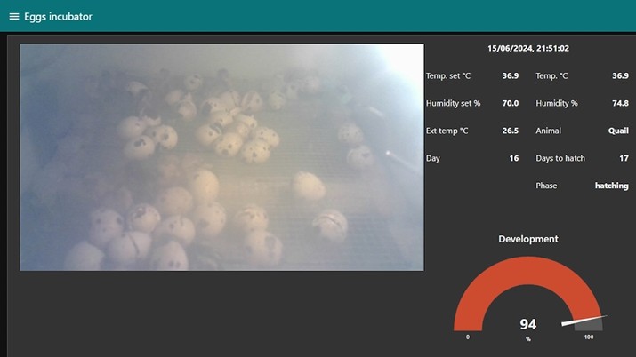
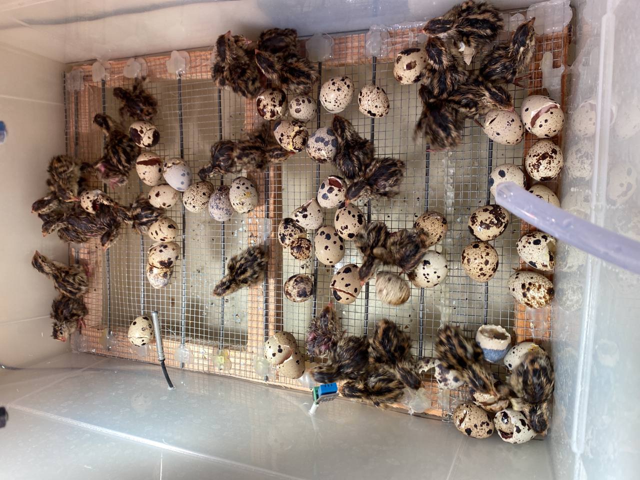
This project was born out of the desire to see if supermarket quail eggs are actually fertile (unlike chicken eggs). The goal was to explore the possibility of incubating quail eggs and monitor their development.
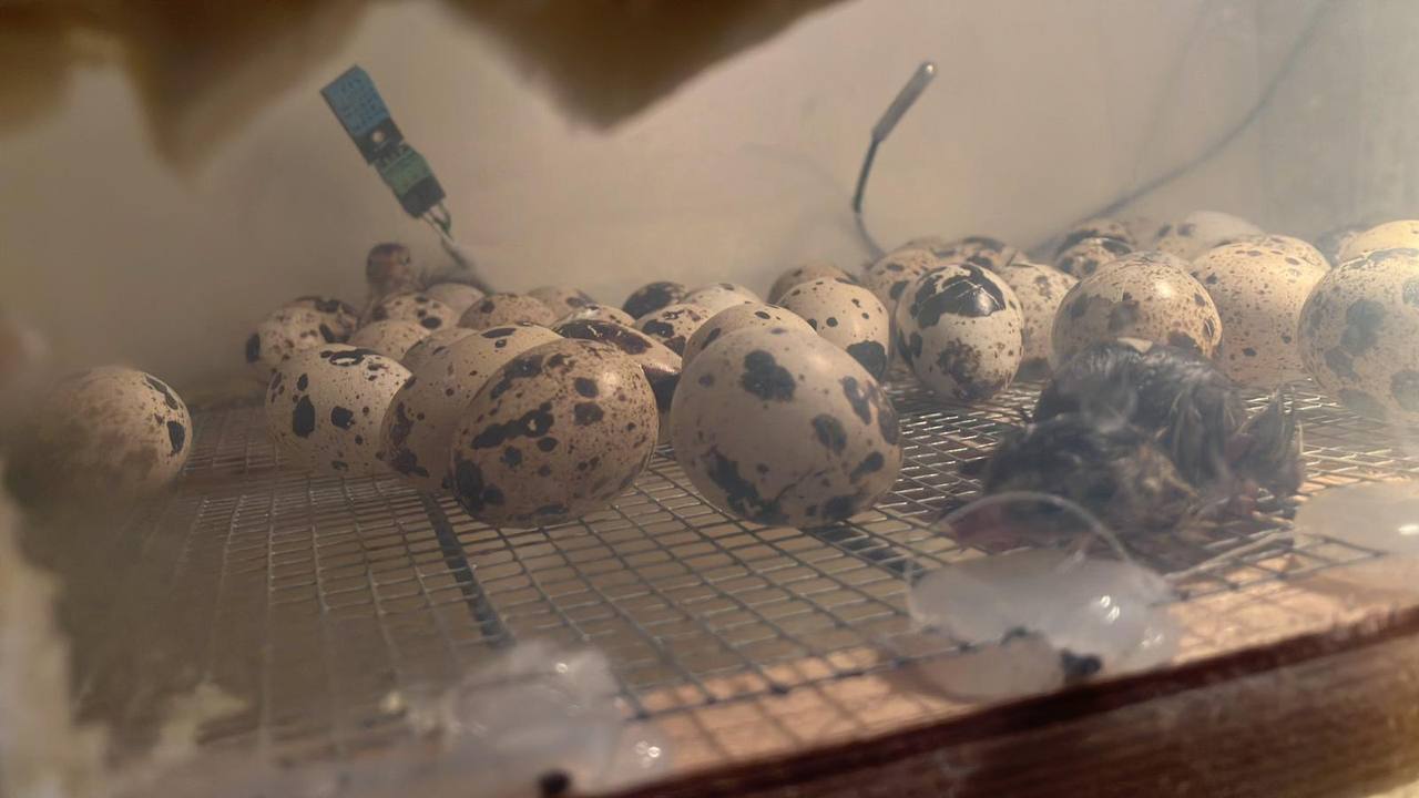
To achieve this, I designed an incubator for birds using a thermally insulated plastic box. The setup is simple but effective for maintaining the right conditions for incubation.
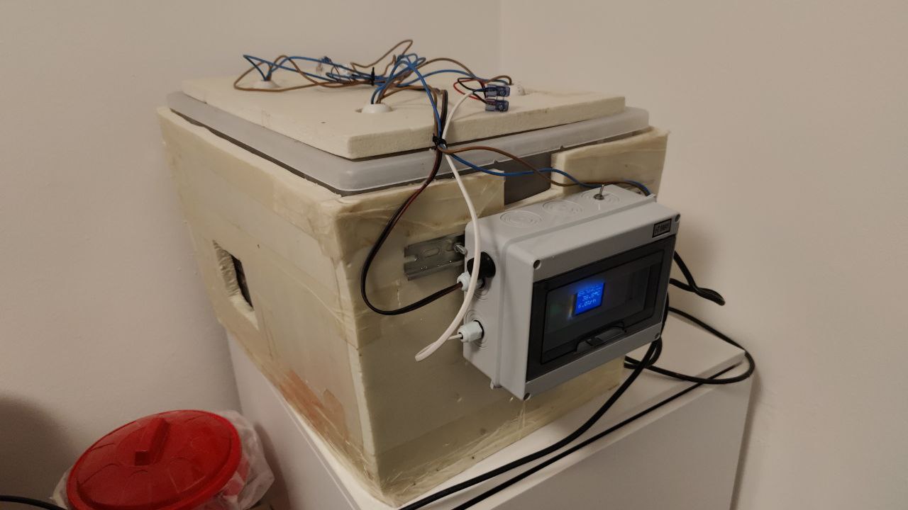
I managed the temperature and humidity control using a custom-designed board that features an ESP32-WROOM chip. This board was programmed using the Arduino IDE, providing full control over the incubator's conditions.
For heating, I used a 220V heater, which I modulated using a trimmer. To maintain proper humidity inside, I used an electric room humidifier.
The board is equipped with a color TFT graphical interface, making it easy to monitor and control the incubator. Additionally, the incubator is controlled directly via a Telegram bot on your phone, allowing for remote management.
For initial setup (WiFi credentials, Telegram token, and password), I added a feature that allows the board to switch to Access Point (AP) mode, enabling configuration through a minimal web server. These values are saved in the non-volatile memory of the ESP32, so they persist through future restarts.
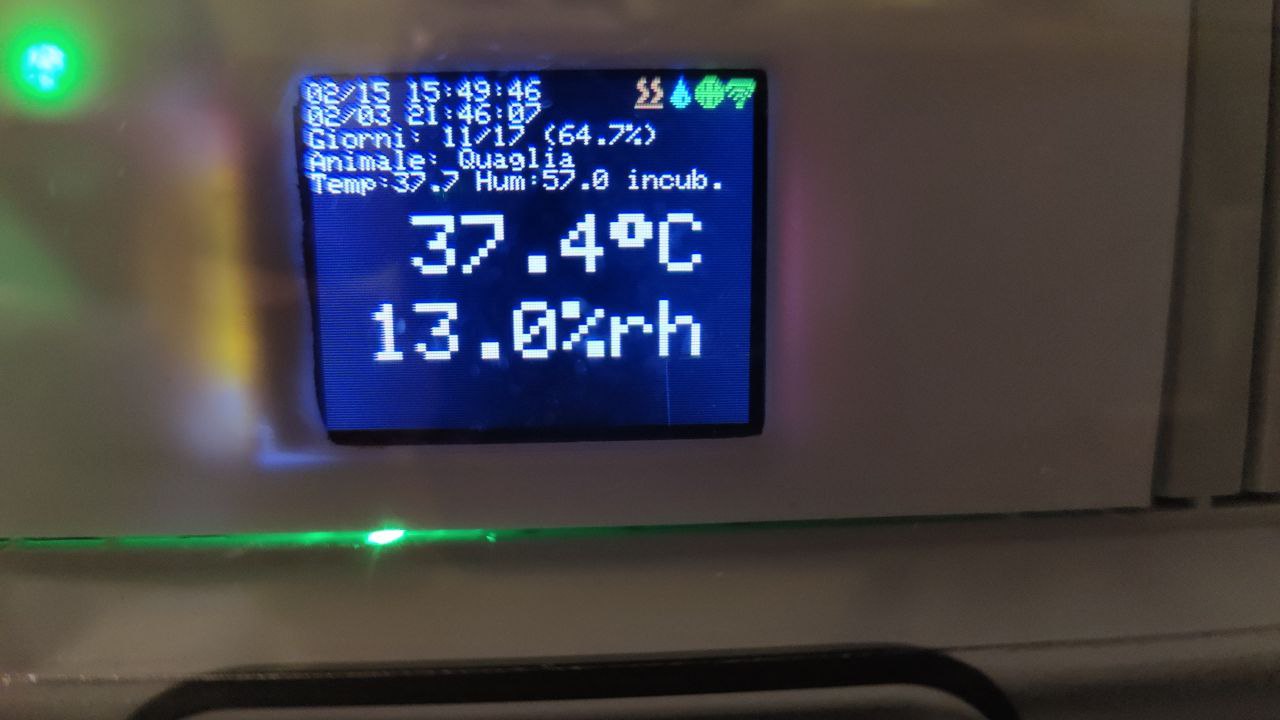
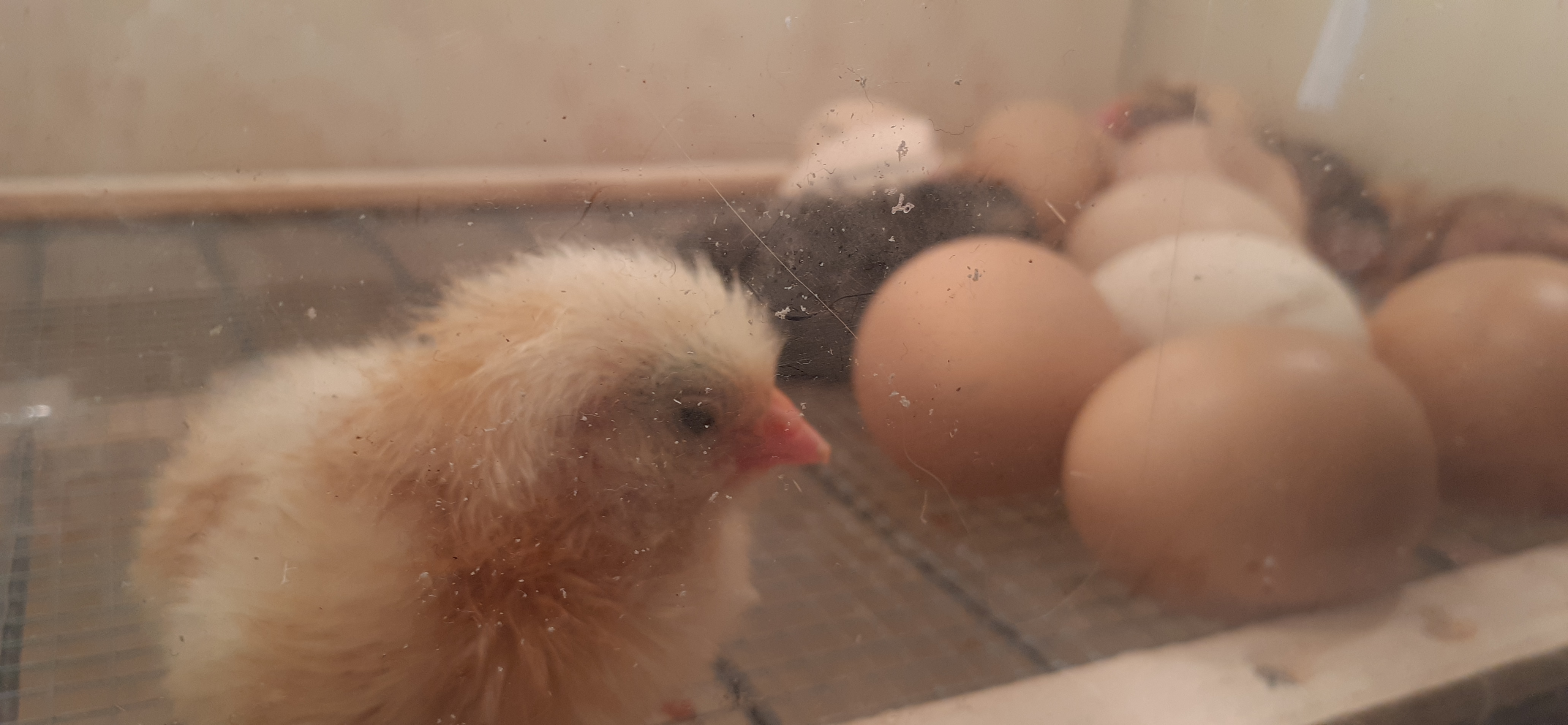
Currently, the software is configured to handle the incubation periods, temperatures, and humidity levels for chickens and quails. However, the system can easily be extended to accommodate other types of birds as well.
The incubator's data can be communicated via MQTT, allowing for remote tracking of the incubation process from an external monitoring environment. I personally use Node-RED to monitor the data in real-time.
To make the project even more enjoyable, I set up a live stream on Twitch of the incubation process. This allows my friends to join in on the excitement and witness the first moments of life for the ❤️chicks❤️.
| Qty | Value | Footprint | References |
|---|---|---|---|
| 6 | R10K | Resistor_SMD:R_1206_3216Metric | R5, R6, R8, R9, R10, R12 |
| 3 | R100 | Resistor_SMD:R_1206_3216Metric | R1, R2, R3 |
| 2 | 1N4148W | Diode_SMD:D_SOD-123 | D5, D6 |
| 2 | BC547 | Package_TO_SOT_THT:TO-92_Inline | Q1, Q2 |
| 2 | BC847 | Package_TO_SOT_SMD:SOT-23 | Q3, Q4 |
| 2 | C_Polarized | Capacitor_THT:CP_Radial_D10.0mm_P5.00mm | C1, C2 |
| 2 | DHT11_EN | Jumper:SolderJumper-2_P1.3mm_Open_RoundedPad1.0x1.5mm | DHT11_EN1, DHT11_EN2 |
| 2 | Diode | Diode_THT:D_DO-35_SOD27_P10.16mm_Horizontal | D2, D3 |
| 2 | FINDER-36.11 | Relay_THT:Relay_SPDT_Finder_36.11 | K1, K2 |
| 2 | R330 | Resistor_SMD:R_1206_3216Metric | R4, R7 |
| 1 | AMS1117-3.3 | Package_TO_SOT_SMD:SOT-223-3_TabPin2 | U3 |
| 1 | BOOT | Button_Switch_THT:SW_PUSH_6mm_H4.3mm | BOOT1 |
| 1 | ESP32-WROOM-32 | RF_Module:ESP32-WROOM-32 | U1 |
| 1 | FLOWMETER | Button_Switch_THT:SW_PUSH_6mm_H4.3mm | FLOWMETER1 |
| 1 | FLOWMETER/NTC | TerminalBlock:TerminalBlock_Altech_AK300-2_P5.00mm | J8 |
| 1 | HLK-PM01 | Converter_ACDC:Converter_ACDC_HiLink_HLK-PMxx | PS1 |
| 1 | I2C connector | Connector_JST:JST_XH_B4B-XH-AM_1x04_P2.50mm_Vertical | J2 |
| 1 | LED | Connector_PinHeader_2.54mm:PinHeader_1x02_P2.54mm_Vertical | LED2 |
| 1 | LED | Jumper:SolderJumper-2_P1.3mm_Open_RoundedPad1.0x1.5mm | LED1 |
| 1 | LED | LED_SMD:LED_1206_3216Metric_Pad1.42x1.75mm_HandSolder | D4 |
| 1 | LED RGB | LED_SMD:LED_RGB_5050-6 | D1 |
| 1 | MAX485E | Package_SO:SO-8_3.9x4.9mm_P1.27mm | U2 |
| 1 | NTC | Jumper:SolderJumper-2_P1.3mm_Open_RoundedPad1.0x1.5mm | NTC2 |
| 1 | NTC | Connector_PinHeader_2.54mm:PinHeader_1x02_P2.54mm_Vertical | NTC1 |
| 1 | NTC2 | Connector_JST:JST_XH_B2B-XH-A_1x02_P2.50mm_Vertical | J10 |
| 1 | OTA | Jumper:SolderJumper-2_P1.3mm_Open_RoundedPad1.0x1.5mm | OTA2 |
| 1 | OTA | Connector_PinHeader_2.54mm:PinHeader_1x02_P2.54mm_Vertical | OTA1 |
| 1 | R1K | Resistor_SMD:R_1206_3216Metric | R11 |
| 1 | RESET | Button_Switch_THT:SW_PUSH_6mm_H4.3mm | RESET1 |
| 1 | RS485/DHT11 | Connector_Phoenix_MSTB:PhoenixContact_MSTBA_2,5_3-G_1x03_P5.00mm_Horizontal | J3 |
| 1 | Relay1 | TerminalBlock:TerminalBlock_Altech_AK300-2_P5.00mm | J4 |
| 1 | Relay2 | TerminalBlock:TerminalBlock_Altech_AK300-2_P5.00mm | J7 |
| 1 | SW_AP | Button_Switch_THT:SW_PUSH_6mm_H4.3mm | SW_AP1 |
| 1 | SW_OTA | Button_Switch_THT:SW_PUSH_6mm_H4.3mm | SW_OTA1 |
| 1 | TFT SPI interface | Connector_JST:JST_XH_B8B-XH-AM_1x08_P2.50mm_Vertical | J1 |
| 1 | TX RX - + | Connector_PinSocket_2.54mm:PinSocket_2x04_P2.54mm_Vertical | J9 |
| 1 | VAC 230V | TerminalBlock:TerminalBlock_Altech_AK300-2_P5.00mm | J5 |
| 1 | VDC 5V | Connector_JST:JST_XH_B2B-XH-A_1x02_P2.50mm_Vertical | J6 |
It measures 96.5 × 81.3 mm and has 2 copper layers, 1.6 mm thick.
53 parts, built around the ESP32-WROOM-32, MAX485ED, HLK-PM01 and AMS1117-3.3. The full list of its parts is on this page, with links to each part's symbol and footprint where PCBKit's library has them.
From the Socketto/Incubator_ESP32 repository on GitHub, at the commit this page was made from: the board is board/Incubator.kicad_pcb and its schematic board/Incubator.kicad_sch. PCBKit opens the board in the browser, with nothing to install.
Its repository states no licence, so its author keeps all rights: ask Socketto before reusing the design.

VinayGopi-PK/ESP32-4-Channel-WiFi-Home-Automation
ESP32-based 4-channel Wi-Fi Home Automation Controller designed in KiCad. Includes schematic, PCB layout, Gerber files, BOM and 3D visualization.


haripradhap14/ESP32-4CH-Relay-Controller-
4-channel IoT relay controller using ESP32-WROOM-32E for home automation.


adarshnarwariya12/PCB_Design
A collection of PCB design projects developed using KiCad.

adivarpe/kicad_designs
in this i attached the multiple designs circuit which is designed from kicad .