6 layers100 × 90 mm

 sneakylizard123-4/Overkill-nRF
A modular RF communication board designed for the Overkill system, built around the nRF24L01+ radio module instead of a bare RF IC + Amplifier.
Overkill nRF is an open-source printed circuit board by sneakylizard123-4, from the sneakylizard123-4/Overkill-nRF repository on GitHub. It is a 4-layer board of 50 × 75 mm with 80 parts on 69 nets, routed with 529 tracks and 97 vias.
It is built around the ESP32-S3-WROOM-1U-N4, TLV75733PDBV and TPD2EUSB30DRT, with the SS14, AO3400A and WS2812B among its other parts. Its parts include 17 resistors, 15 capacitors, 14 connectors, 11 diodes and 8 switches. It belongs with the ESP32 boards of this library.


A modular RF communication board designed for the Overkill system, built around the nRF24L01+ radio module instead of a bare RF IC + Amplifier. This makes the design easier to assemble, debug, and iterate while keeping it fully modular inside the Overkill ecosystem.
The Overkill nRF Board handles wireless communication for the system using nRF24L01+ modules.
It is designed to be:
Connection to Overkill system via JST-PH connector:
This board prioritizes:
The goal is fast iteration for RF experimentation inside the Overkill platform.
All pictures and screenshots should be in the images/ folder.
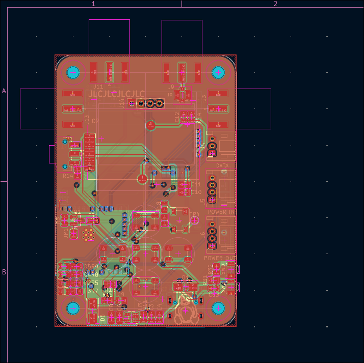
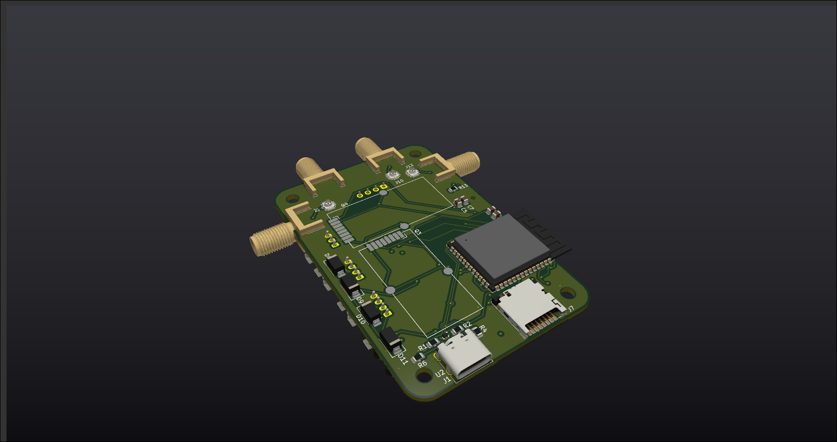
Top-side render (ray-traced KiCad):
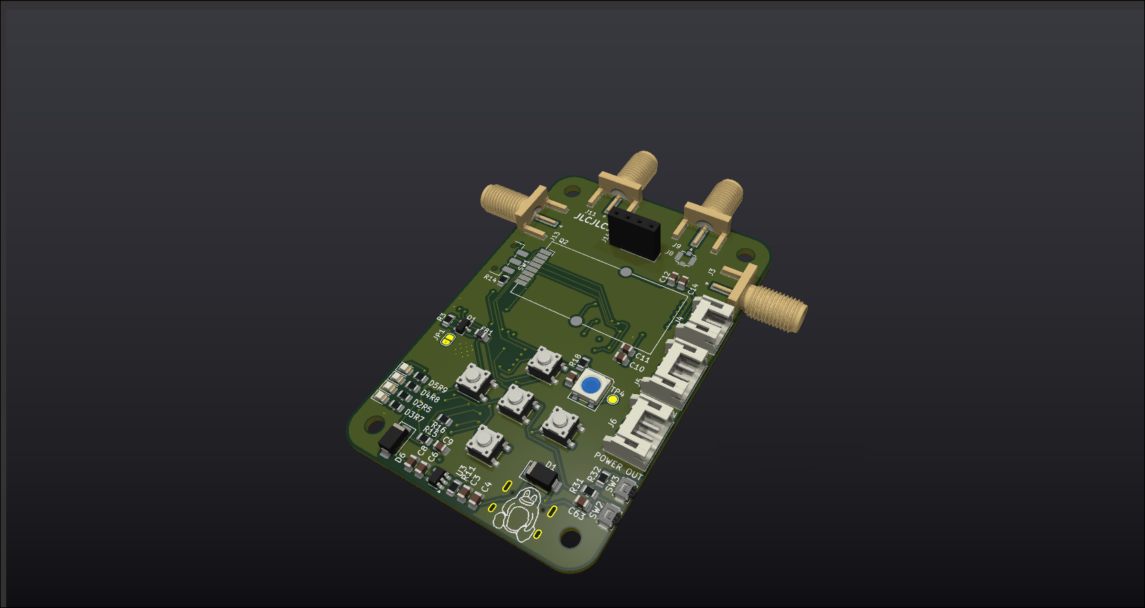
Bottom-side render (ray-traced KiCad):
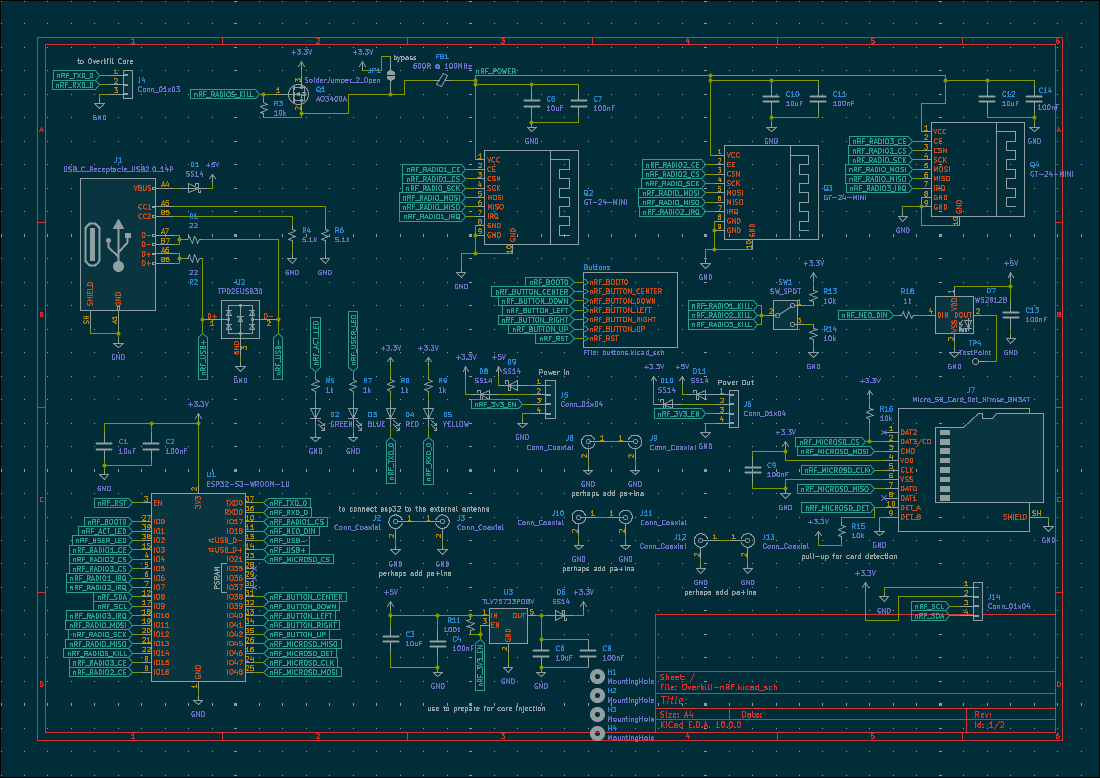
schematic sheet 1:
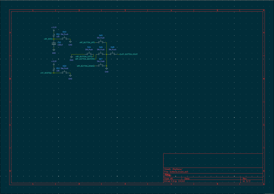
schematic sheet 2:
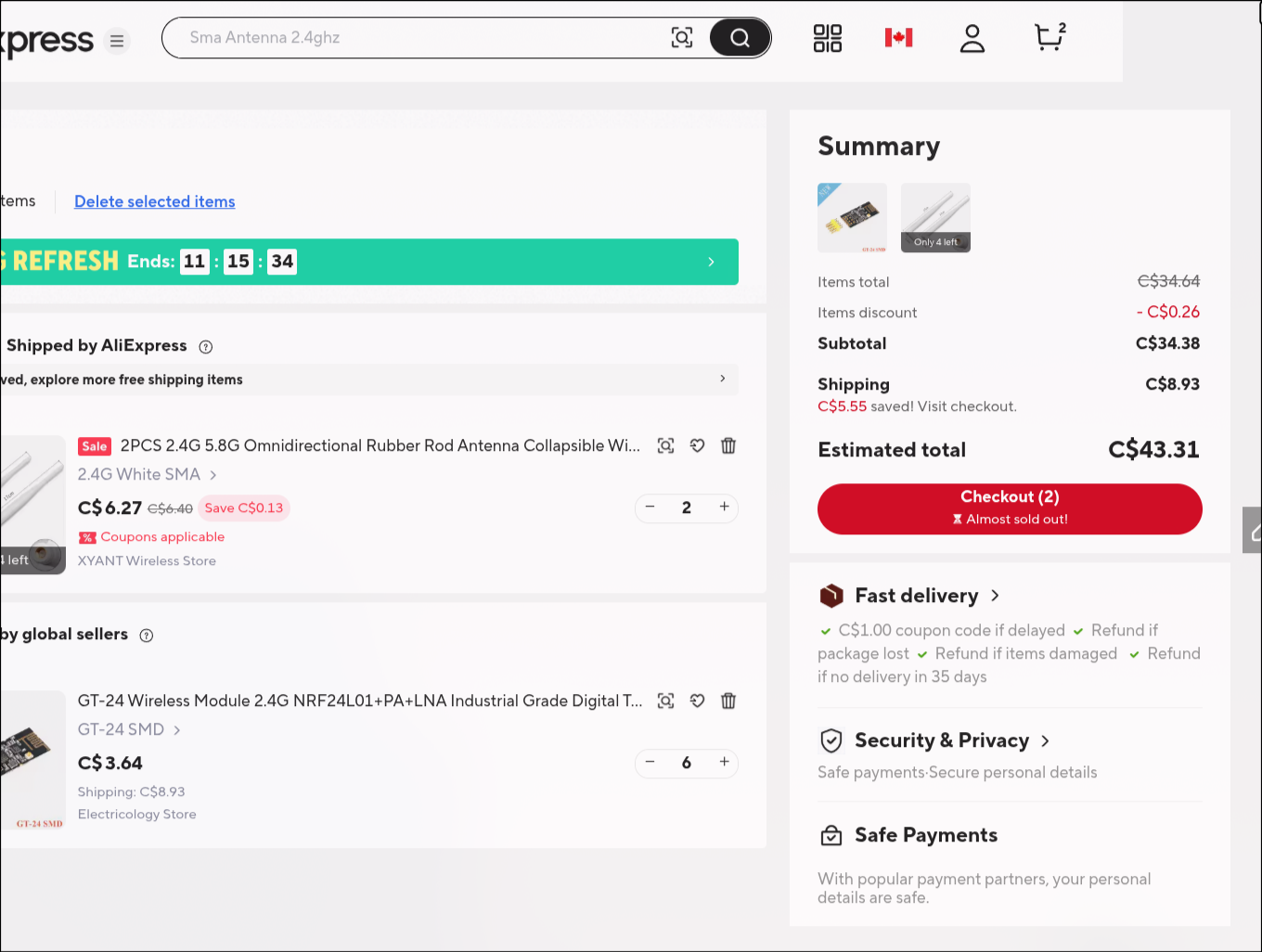
AliExpress cart:
LCSC sourcing carts:



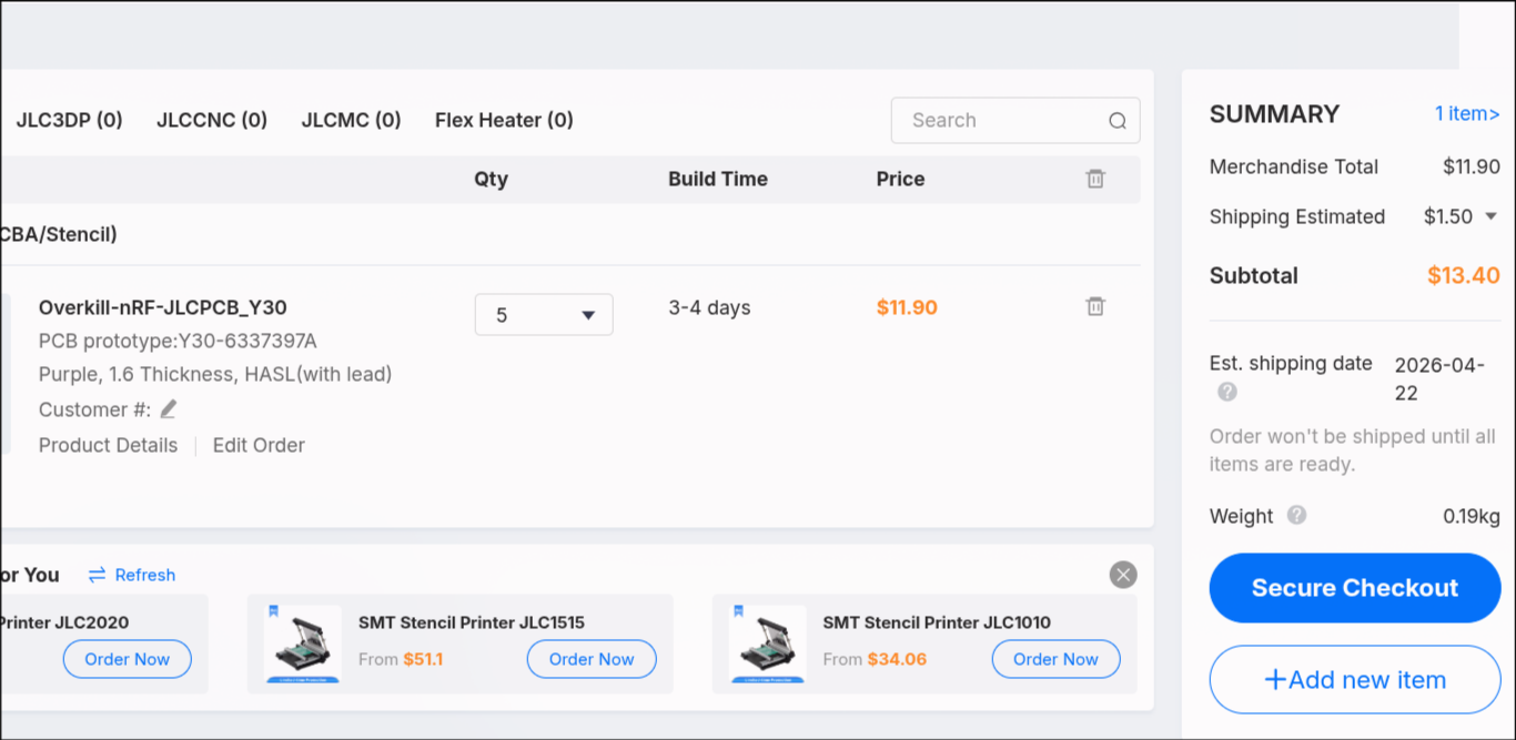
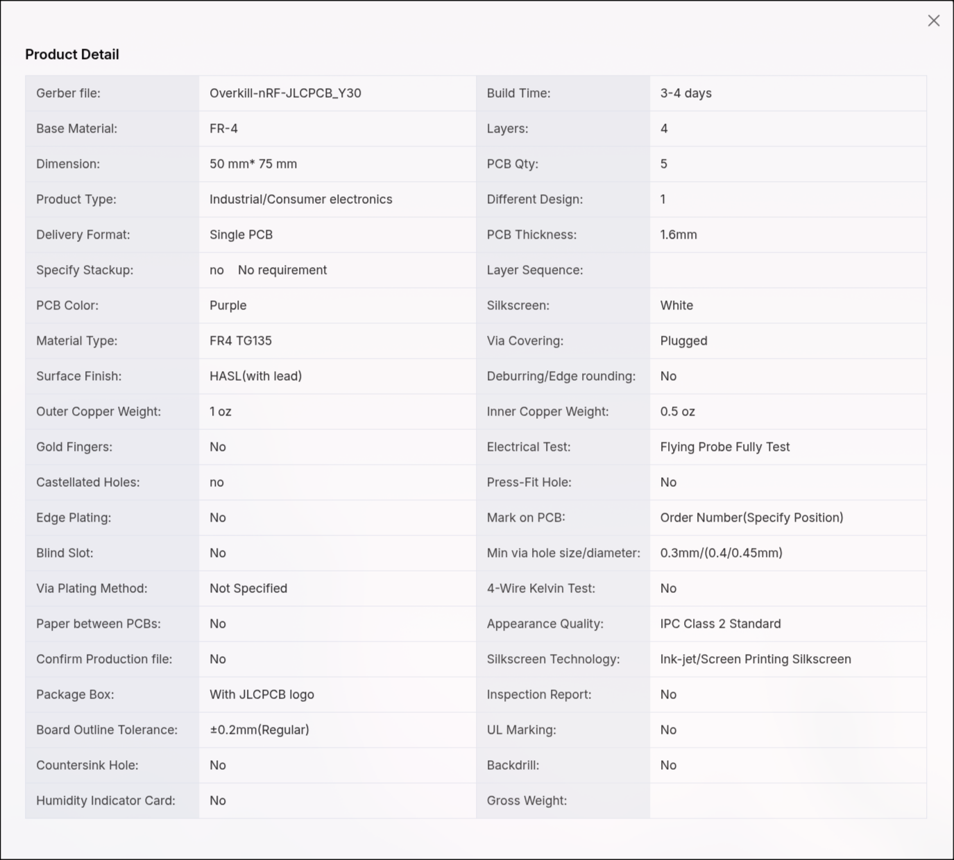
JLCPCB cart:
 or maybe PCBWay if they sponsor this project too!
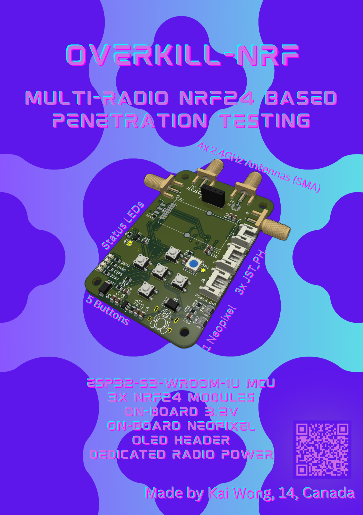
The board connects into the Overkill system via JST-PH and is designed to interface with:
Other parts of the system are being developed separately.
A full BOM is included in the repository. see bom.csv for details.
It includes:
This revision prioritizes usability and fast iteration over RF optimization complexity. The goal is to make RF experimentation inside the Overkill system fast, modular, and actually enjoyable to play with.
| Qty | Value | Footprint | References |
|---|---|---|---|
| 9 | 100nF | Capacitor_SMD:C_0805_2012Metric | C2, C4, C7, C8, C9, C11, C13, C14, C63 |
| 7 | 10k | Resistor_SMD:R_0805_2012Metric | R3, R13, R14, R15, R16, R31, R32 |
| 6 | 10uF | Capacitor_SMD:C_0805_2012Metric | C1, C3, C5, C6, C10, C12 |
| 6 | SS14 | Diode_SMD:D_SMA | D1, D6, D8, D9, D10, D11 |
| 5 | 1k | Resistor_SMD:R_0805_2012Metric | R5, R7, R8, R9, R18 |
| 5 | SW_Push | Button_Switch_SMD:SW_SPST_PTS647_Sx38 | SW4, SW5, SW6, SW7, SW8 |
| 4 | Conn_Coaxial | Connector_Coaxial:SMA_Amphenol_132289_EdgeMount | J3, J9, J11, J13 |
| 4 | Conn_Coaxial | Connector_Coaxial:U.FL_Molex_MCRF_73412-0110_Vertical | J2, J8, J10, J12 |
| 4 | MountingHole | MountingHole:MountingHole_3.2mm_M3 | H1, H2, H3, H4 |
| 3 | GT-24-MINI | Overkill-nRF:nRF24L01-GT24_Breakout | Q2, Q3, Q4 |
| 2 | 22 | Resistor_SMD:R_0805_2012Metric | R1, R2 |
| 2 | 5.1k | Resistor_SMD:R_0805_2012Metric | R4, R6 |
| 2 | Conn_01x04 | Connector_JST:JST_PH_S4B-PH-K_1x04_P2.00mm_Horizontal | J5, J6 |
| 2 | SW_Push | Button_Switch_SMD:SW_SPST_B3U-3000P | SW2, SW3 |
| 1 | 100k | Resistor_SMD:R_0805_2012Metric | R11 |
| 1 | 600R @ 100MHz | Inductor_SMD:L_0805_2012Metric | FB1 |
| 1 | AO3400A | Package_TO_SOT_SMD:SOT-23 | Q1 |
| 1 | BLUE | LED_SMD:LED_0805_2012Metric | D3 |
| 1 | Conn_01x03 | Connector_JST:JST_PH_S3B-PH-K_1x03_P2.00mm_Horizontal | J4 |
| 1 | Conn_01x04 | Connector_PinSocket_2.54mm:PinSocket_1x04_P2.54mm_Vertical | J14 |
| 1 | ESP32-S3-WROOM-1U | RF_Module:ESP32-S3-WROOM-1U | U1 |
| 1 | GREEN | LED_SMD:LED_0805_2012Metric | D2 |
| 1 | LOGO | Overkill-nRF-Parts:linuxpenguin | G*** |
| 1 | Micro_SD_Card_Det_Hirose_DM3AT | Connector_Card:microSD_HC_Molex_104031-0811 | J7 |
| 1 | RED | LED_SMD:LED_0805_2012Metric | D4 |
| 1 | SW_SPDT | Button_Switch_SMD:SW_SPDT_CK_JS102011SAQN | SW1 |
| 1 | SolderJumper_2_Open | Jumper:SolderJumper-2_P1.3mm_Open_RoundedPad1.0x1.5mm | JP1 |
| 1 | TLV75733PDBV | Package_TO_SOT_SMD:SOT-23-5 | U3 |
| 1 | TPD2EUSB30 | Package_TO_SOT_SMD:Texas_DRT-3 | U2 |
| 1 | TestPoint | TestPoint:TestPoint_Pad_D1.5mm | TP4 |
| 1 | USB_C_Receptacle_USB2.0_14P | Connector_USB:USB_C_Receptacle_HRO_TYPE-C-31-M-12 | J1 |
| 1 | WS2812B | LED_SMD:LED_WS2812B_PLCC4_5.0x5.0mm_P3.2mm | D7 |
| 1 | YELLOW | LED_SMD:LED_0805_2012Metric | D5 |


JunOllyLi/TX_PCB
NOTE: the latest PCB had been manufactured was v2.0. But it had the Gimbal ZH-connector reversed. The schematics and PCB drawing had been updated to v2.1 to fix that. But v2.1 had not been really manufactured yet.


igorilla666/water-controller
Scheda di controllo basata sul modulo Waveshare ESP32-S3-ETH, con ingressi sensore, RS-485, pilotaggio rele, buzzer e alimentazione/protezioni dedicate.

machadoleonardo94/lux-et-tenebris
Devkit for LED strips, with wide range of voltage inputs, and options for current limited outputs

electromotif208/pcb-portfolio
👨💻 Electronics Engineer 📺 YouTube: ELECTROMOTIF 🔧 Tools: KiCad, EasyEDA 📡 Domains: Power Supply, ESP32, IoT, Embedded Hardware
It measures 50 × 75 mm and has 4 copper layers, 1.6 mm thick.
80 parts, built around the ESP32-S3-WROOM-1U-N4, TLV75733PDBV, TPD2EUSB30DRT and SS14. The full list of its parts is on this page, with links to each part's symbol and footprint where PCBKit's library has them.
From the sneakylizard123-4/Overkill-nRF repository on GitHub, at the commit this page was made from: the board is kicad/Overkill-nRF.kicad_pcb and its schematic kicad/Overkill-nRF.kicad_sch. PCBKit opens the board in the browser, with nothing to install.
Its repository states no licence, so its author keeps all rights: ask sneakylizard123-4 before reusing the design.