2 layers
ArduinoPC
slu4coder/Arduino-Nano-PC
1 Arduino Nano + 1 Logic Chip = Personal Computer with VGA and PS/2
17 parts49
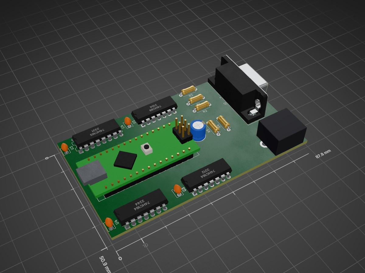
 slu4coder/Arduino-Nano-PC49
1 Arduino Nano + 1 Logic Chip = Personal Computer with VGA and PS/2
ArduinoPC is an open-source printed circuit board by slu4coder, from the slu4coder/Arduino-Nano-PC repository on GitHub. It is a 2-layer board with 17 parts on 57 nets.
It is built around the 74HC164, 74HC165D and 74HC86D. Its parts include 5 capacitors, 5 resistors, 4 ICs and 2 connectors. It belongs with the AVR (ATmega, ATtiny) boards of this library.


I am pushing the limits of how much compute you can get out of an Arduino Nano:
    o 320x200 pixels of monochrome VGA output (optional: 16 row colors)

    o PS/2 keyboard readout

o requires only 1(!) logic IC 74HC166Set the Nano's fuses for output of the 16MHz system clock on pin D8 (see appendix A below).
Copy the library files 'os.h' and 'os.S' into a folder '../Arduino/libraries/os'.
Start a new sketch with '#include <os.h>'. The following global variables and functions are available:
 int os::frames                                        built-in 16-bit 60Hz frame counter

 byte os::vram[25][40]                                 character video RAM array

 byte os::cram[25]                                     row color RAM array, available colors are:

                                                       WHITE, BLACK, GRAY, RED, GREEN, YELLOW, BLUE, MAGENTA, CYAN,

                                                       DKGRAY, DKRED, DKGREEN, DKYELLOW, DKBLUE, DKMAGENTA, DKCYAN.

 os::text(String s, byte x, byte y, byte col = 0)      prints text at screen position (x, y), col = 0: don't set row color

 os::fill(char c = 32)                                 fills the video RAM with character c

 os::scroll()                                          scrolls the video RAM one step upwards

 os::wait(int n)                                       waits for n frames

 byte os::getkey()                                     returns keystroke ASCII code (none: 0)
26KB FLASH (1KB SRAM) of the Nano's 30KB FLASH (2KB SRAM) are usable, respectively. To save SRAM, define constant variables in FLASH memory by adding PROGMEM to the data type. Constant string arguments can be defined in FLASH by using the F("...") macro.
Have fun!
APPENDIX
A. Setting Arduino Nano's fuse bytes via ISP (in-situ programming) for output of system CLK
o Connect two Arduino Nanos in the following way (programmer -> target): D13 -> D13, D12 -> D12, D11 -> D11, D10 -> RESET, 5V -> 5V, GND -> GND
o Arduino IDE: Upload sketch 'examples/ArduinoISP' into programmer and select 'Tools/Programmer/Arduino as ISP'.
o Open the file 'C:\Program Files (x86)\Arduino\hardware\arduino\avr\boards.txt'.
o In section '## Arduino Nano w/ ATmega328P' (line 141), change line 149 'nano.menu.cpu.atmega328.bootloader.low_fuses=0xFF' (default) to '...=0xBF' (output system CLK on Pin D8 (B0)) and save the file.
o Close and re-open the Arduino IDE for the changes to become active.
o Select target board: 'Arduino Nano', processor: 'AtMega328P' and 'Tools/Burn bootloader'.
B. Hardware
Pin A0 (C0): keyboard input CLK
Pin A1 (C1): keyboard input DAT
Pin A2-5 (C2-5): 4-bit color output to 74HC08 (optional)
Pin D0-7 (D0-7): 8-bit pixel output to 74HC166
Pin D8 (B0): CLKO (16MHz system clock output)
Pin D9 (B1): unused
Pin D10 (B2): /VSYNC VGA (timer1, every 1/60s)
Pin D11 (B3): /PE 74166 pixel shift register synchroneous parallel load on rising edge of CP
Pin D12 (B4): /HSYNC VGA (inside ISR, every 32µs)
Pin D13 (B5): LED
| Qty | Value | Footprint | References |
|---|---|---|---|
| 4 | 100n | Capacitor_THT:C_Disc_D3.8mm_W2.6mm_P2.50mm | C1, C2, C3, C4 |
| 3 | 220 | Resistor_THT:R_Axial_DIN0207_L6.3mm_D2.5mm_P7.62mm_Horizontal | R3, R4, R5 |
| 2 | 68 | Resistor_THT:R_Axial_DIN0207_L6.3mm_D2.5mm_P7.62mm_Horizontal | R1, R2 |
| 2 | 74HC164 | Package_DIP:DIP-14_W7.62mm | U2, U4 |
| 1 | 47µ | Capacitor_THT:CP_Radial_D6.3mm_P2.50mm | C5 |
| 1 | 74HC165 | Package_DIP:DIP-16_W7.62mm | U3 |
| 1 | 74HC86 | Package_DIP:DIP-14_W7.62mm | U1 |
| 1 | Arduino_Nano_v3.x | Module:Arduino_Nano | A1 |
| 1 | PS/2 Keyboard | ArduinoPC:FP_MINI_DIN_6_PS2 | J1 |
| 1 | VGA DB15 HD Connector (Female) | Connector_Dsub:DSUB-15-HD_Female_Horizontal_P2.29x1.98mm_EdgePinOffset3.03mm_Housed_MountingHolesOffset4.94mm | J2 |
slu4coder/Arduino-Nano-PC
1 Arduino Nano + 1 Logic Chip = Personal Computer with VGA and PS/2

slu4coder/Arduino-Nano-PC
1 Arduino Nano + 1 Logic Chip = Personal Computer with VGA and PS/2

slu4coder/Arduino-Nano-PC
1 Arduino Nano + 1 Logic Chip = Personal Computer with VGA and PS/2

slu4coder/Minimal-UART-Computer-1-2
Legacy: Version 1 and 2 of my TTL-only CPU featuring UART I/O, an expansion port, 512KB SSD at up to 10MHz clock speed


TBMGIT-HUB/CircuitsCourses
Ce projet consiste à réaliser un jeu électronique de Shifumi (Pierre–Feuille–Ciseaux) sur un PCB conçu avec KiCad.

17 parts, built around the 74HC164, 74HC165D and 74HC86D. The full list of its parts is on this page, with links to each part's symbol and footprint where PCBKit's library has them.
From the slu4coder/Arduino-Nano-PC repository on GitHub, at the commit this page was made from: the board is Rev1/Color/KiCAD/ArduinoPC.kicad_pcb and its schematic Rev2/KiCAD (color)/ArduinoPC.kicad_sch. PCBKit opens the board in the browser, with nothing to install.
Its repository states no licence, so its author keeps all rights: ask slu4coder before reusing the design.